


![]()
![]()
![]()
![]()
![]()
![]()
![]()
![]()
![]()
![]()
- Update 11/21/02 -
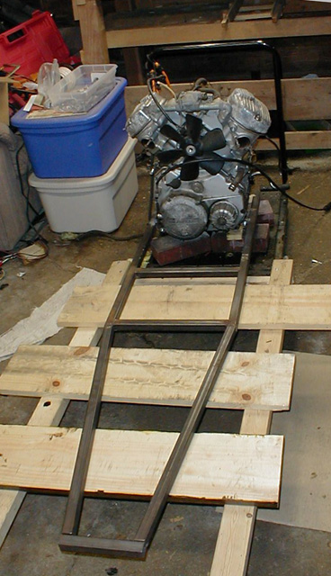
Here was our last starting point. Here the Frame Bottom is mounted to the Engine. After redesigning to take into account the smaller rear wheel size, the frame bottom had to be extended 4 inches and the engine mounting brackets moved back 4 inches.
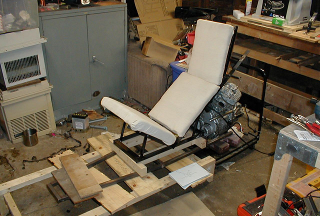
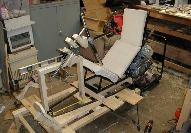
Here is one of the things that has kept me occupied over the past few weeks. here is a fully adjustable full size chair that I built to test the seating angles of the final seat of the bike. This was important for multiple reasons, 1) I could not accurately model how much a person sinks into a chair in my 3D design program and 2) I could not tell what, exactly, would be comfortable, until I built in it and set it in. For those reasons I decided to design and build a completely adjustable chair first, determine what is comfortable change the design of the bike accordingly. I certainly didnt want to have the whole bike finished, and then sit in it only to find it quite uncomfortable. That being said, I still havent done any 'extended sitting' tests. I was glad I went through this effort, as the angles and dimension I guessed at were quite off from a comfortable head supporting seat, and some major changes had to be made in the design to accomodate the new data.
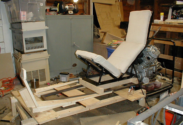
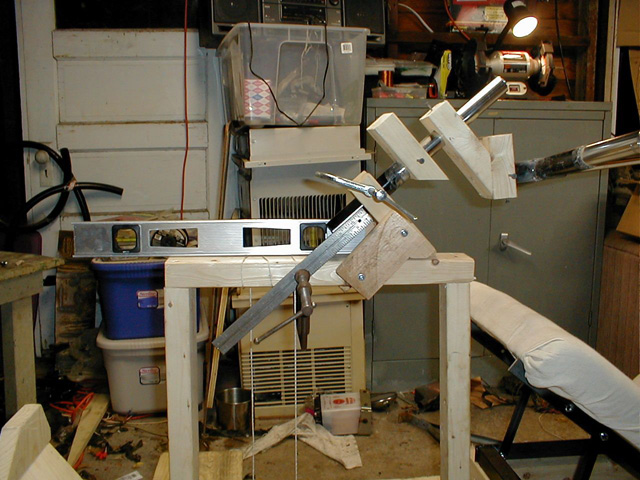
With that information in mind, I went ahead and decided to build a complete 'ergonomic' mockup of the bike, that is, where I would sit, foot rests, and steering column and handlebars. Here you can see one of the foot rests made of wood to test its location and size.
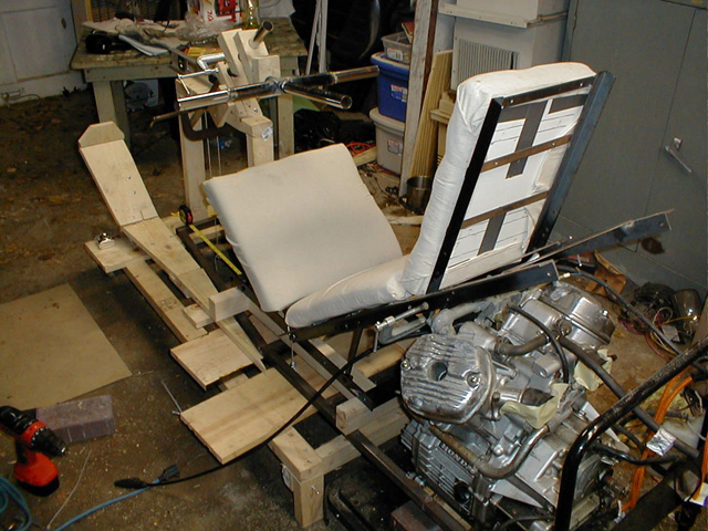
Now the full size steering column mockup and handlebars are in place.
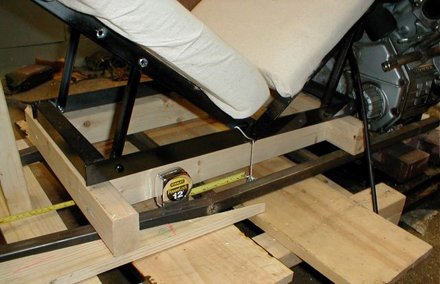
Here the axis where the rear of the seat and the base of the seat meet is supposed to be 3.25" from the front horizontal bar and 3.5" up from there.
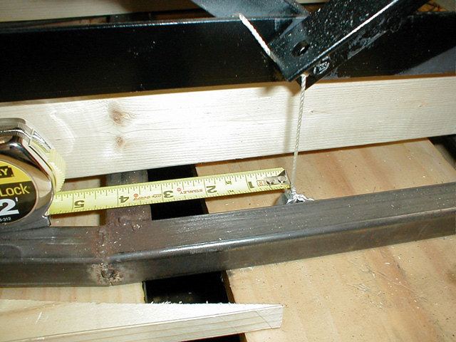
Here you can see, 3.25", almost perfect! This, incendtly, is NOT the final chair, this is just a mockup. In fact I will be using this as my computer chair when I am done with it for my bike. Its quite comfortable!
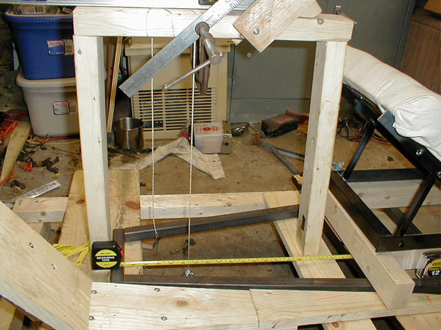
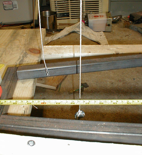
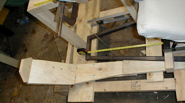
Here the steering column mockup is shown, the front of the seat, and the foot rests. The steering column axis is supposed to cross a point that is 21.5" from the front horizontal cross bar on the frame bottom and 19" up from it.
21.5" ! The vertical dimension came out perfect as well, but I couldnt take a picture of it while measuring it.
Now the rest of the steering column is in place, this is adjustable in multiple places to make sure I can find the most comfortable steering position. The handle bar position slides forward and back on the steering column, and the horizontal mount can slide, and the handlebars themselves can slide forward and back. Here you can also see the level.
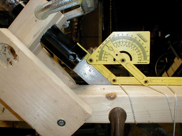
The measured steering column / Handlebar angle is 43º, just as planned. (note, this is just the handlebar rotational axis angle, there will be a ujoint connecting the handlebars to the steering column, so this angle will be adjustable as well. Tilt steering!
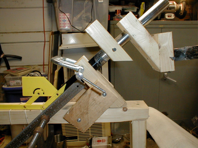
A closer view of the assembled mockup
A better view of the foot rests
The whole assembly
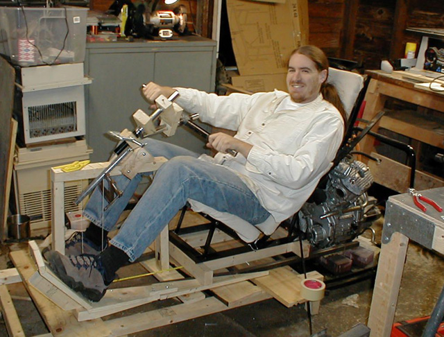
Me on the mockup up at a 35º turn - Back to Status - To Next Update - |
![]()
![]()
![]()