


![]()
![]()
![]()
![]()
![]()
![]()
![]()
![]()
![]()
![]()
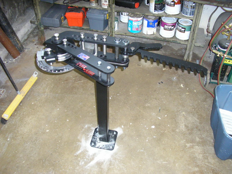
- Update 05/29/2009 - It's been a long time since my last update and there's been quite a bit going on and some significant progress. First, some new tools. For tube bending, which is necessary for frame construction, I bought the PRO TOOLS Model 105 tubing bender
As well as one of their tubing notchers
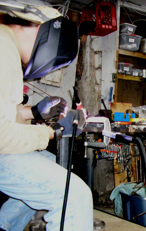
Next up was a Miller TIG Welder, which I've been eyeing for about 3 years now.
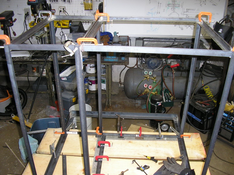
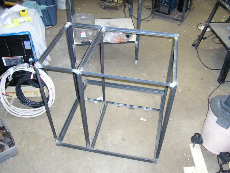
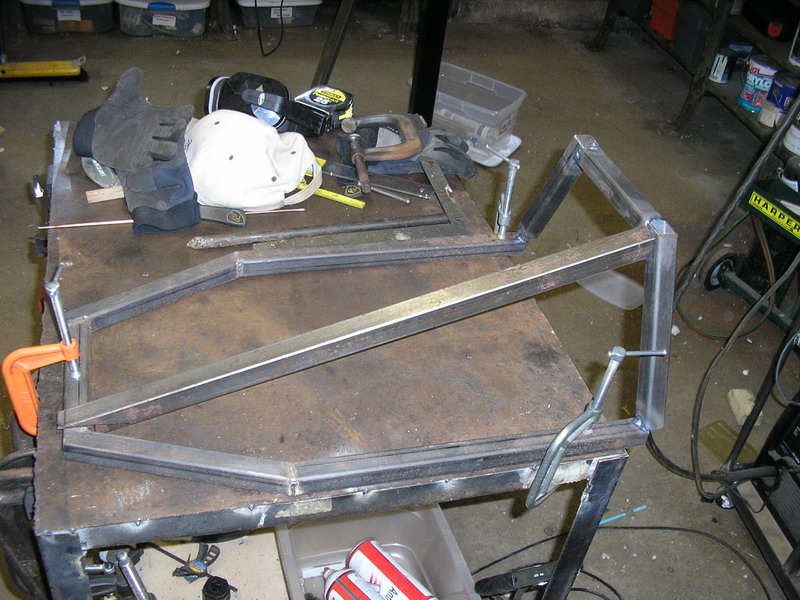
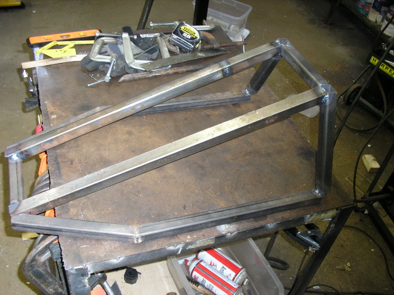
My existing welding cart, which only held a small Miller MIG welder and my plasma torch was obviously not enough for this monster. Here's the new welding cart jigged and waiting for welding. After welding
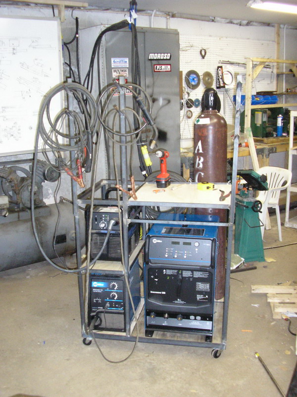
The finished assembly, nice!
Me, trying out the new TIG Welder
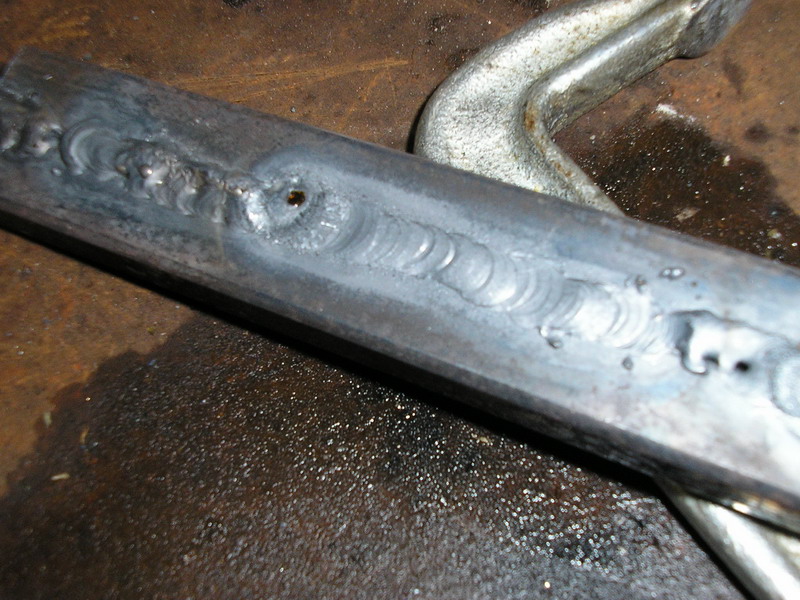
1st attempt, I was very impressed, it was like spreading butter. TIG Welders give you much more control over the variables of the welding, you can alter the heat being applied to your work area seperately from the rate of feed of the metal being applied and the thickness of the filler metal, but the whole welding process is more complex than the quick and simple MIG welding.
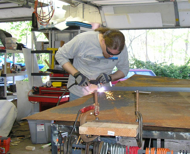
First project after that was to get a new workbench made, which will be necessary for some of the large complex parts coming up (such as the single sided swingarm) First up, cutting the top to my new workbench with the plasma torch
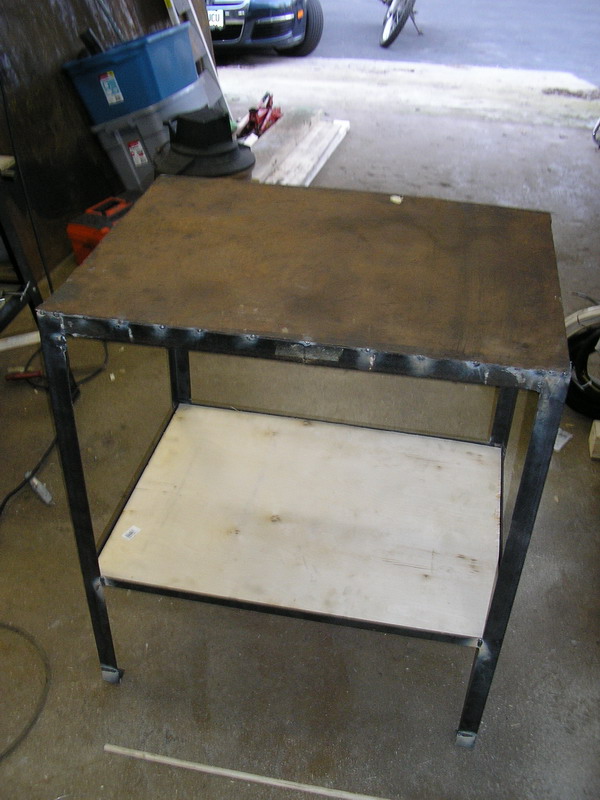
And then the finished workbench, these are heavy duty workbenches. The top is made of angle steel welded into a rectangle but then filled with concrete.
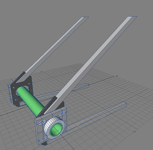
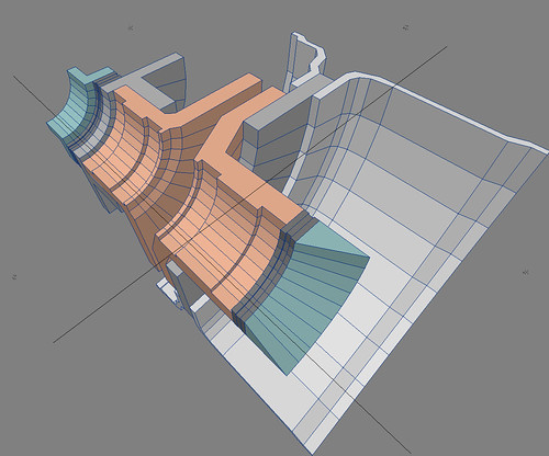
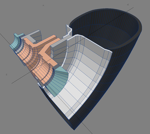
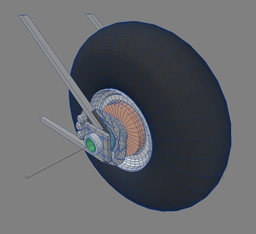
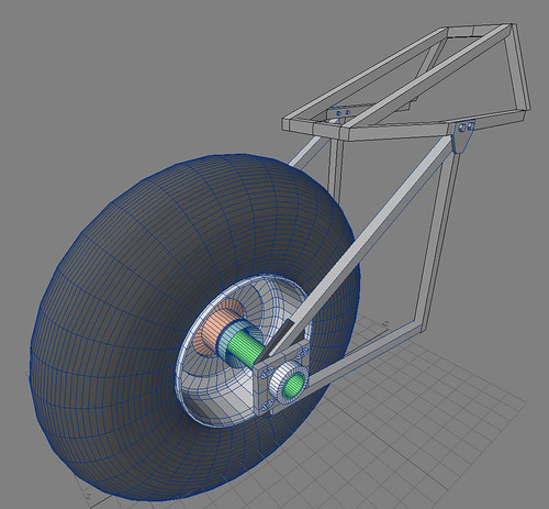
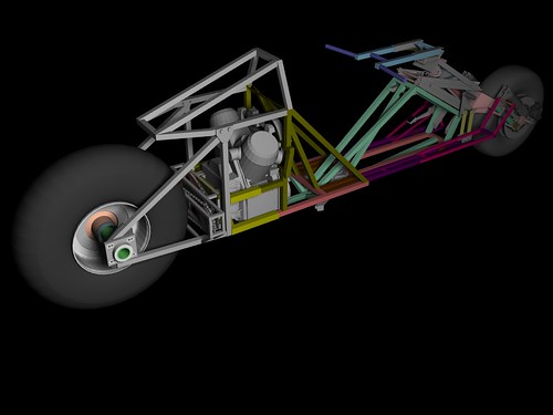
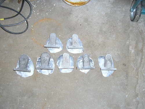
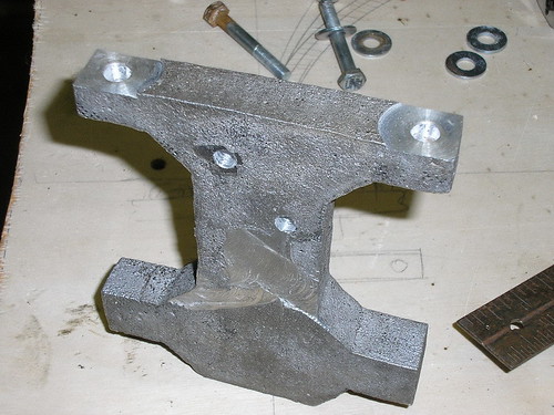
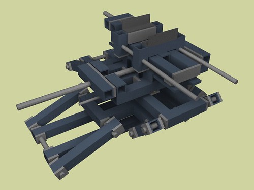
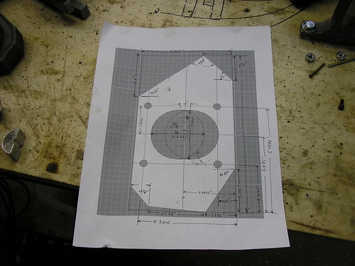
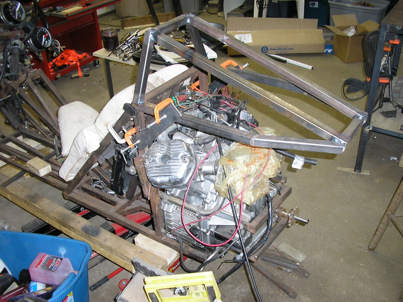
Ok, on to the bike project! The next major step is getting the rear wheel mounted and drive system completed. Here is the rear wheel mounting assembly, it's a hard tail since this is just a prototype. This is the last step to get my power prototype to a rolling chassis status. This essentially constitutes a rigid mounted rear wheel (no suspension) with a large hollow spindle (the green tube) The grey square tubes will be 1" mild square tubing, .125" wall thickness, the dark grey plates that intersect those will be welded to the tubes and made up of 3/8" mild steel plating. A large oval will be cut into that to make room for some small adjusting of the spindle (and thus the plane of rotation for the wheel) with respect to it's perpendicularity to the longitudinal axis of the bike. Shims will be used to line up the hub on the spindle along the left to right axis. The biggest piece to complete are the light grey brackets which are bolted to the dark gray plates, those brackets are what will slide forward or back, and the spindle will rest inside them. I'll be casting those parts out of aluminum. Here is a partial cross section of parts of the rear wheel hub, which will actually hold the wheel + tire on the spindle. The white part is the rim of the wheel. The light grey and orange are both cast aluminum parts that will need to be machined. The dark grey are thrust bearings to the wheel can be held rigidly at the center of the bike. Green parts are also castings that press against the inside of the aluminum brackets mentioned above. Some parts are left out of this, including the radial bearings, but you can see where they will go, in the grooves in the orange hub pieces. Here is the same image but with a quarter section of the tire as well. Tire + Wheel + hub and rear frame. Also in this image is the brake rotor and 3 pot caliper. With the rest of the rear frame pieces I still need to make Ultimately the whole thing will look something like this! very cool Unfortunately, all of these parts will absolutely require the ability to machine them, and my lathe is just not capable of doing what needs to be done on these parts. Here are some other parts, these are brackets for mounting and testing other components of the design. As you can see the casts came out quite well.
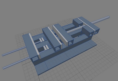
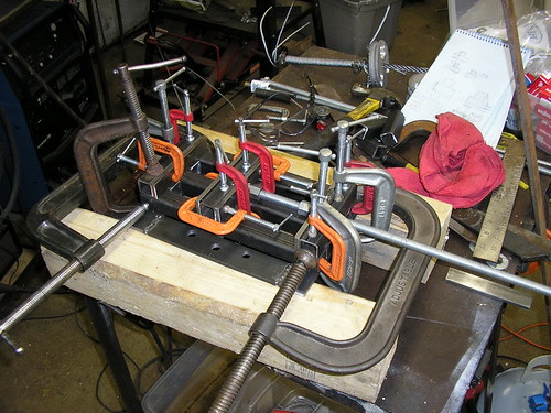
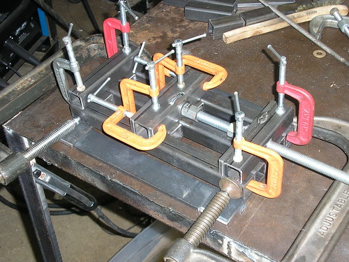
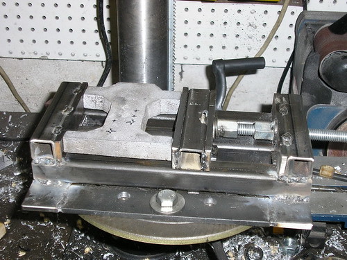
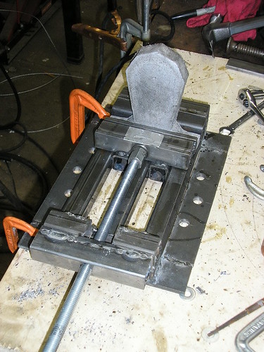
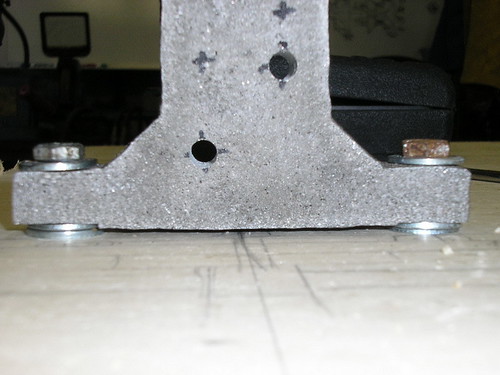
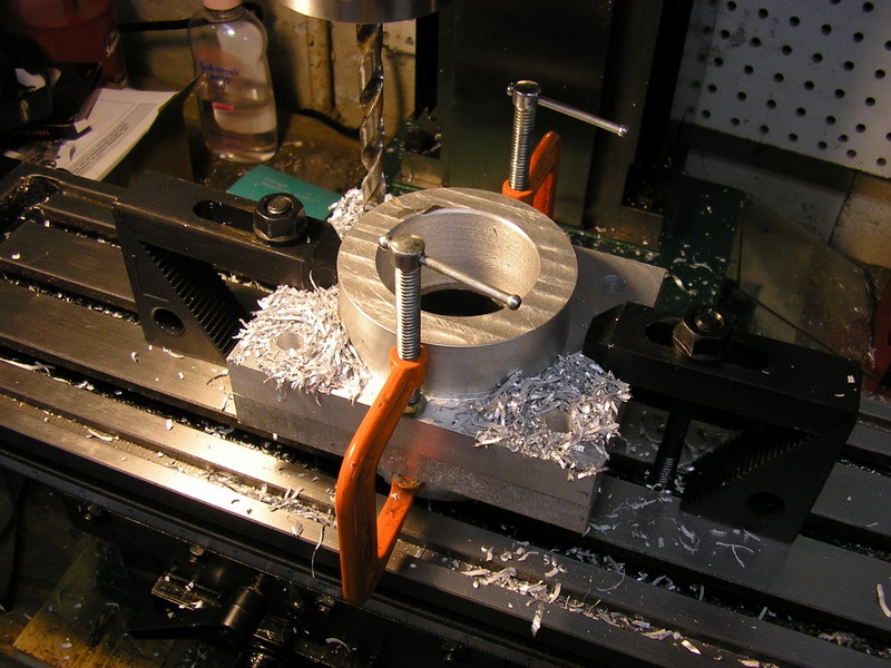
While I can cast parts near to their final size, it's no where near the accuracy needed or that a decent lathe / mill could handle. The mounting brackets need a reasonably high degree of accuracy so they must be machined after casting. Here is the result of my recent castings. Unfortunately the mounting brackets were too large for my drill press vise So… I designed a new vice. In machining metal parts, rigidity is absolutely critical. Flexing or vibration reduces the accuracy of the machining operations significantly. Machining equipment usually achieves it’s rigidity from large cast steel parts, which tend to weigh hundreds of pounds. I personally find this a little annoying, the stresses placed on the metal which make up the machining equipment are no where near the limits of the parts, all that metal is there just for stiffness and most is unnecessary. This makes a decent vise weigh 85 lbs, and small milling machine weigh 400 or more pounds. I’d be interested to see some aluminum based machining equipment for starters, but beyond that, rigidity and stiffness can be achieved just as well through beams and trusses without all that extra weight. With that in mind, having a lot of extra metal around, and eager to continue working, I designed a quick vice using 1” square steel tubes and 1” x ¼” cold rolled steel bars. After some cutting and a plentiful supply of C clamps – a machinists / welders best friend - it’s ready to weld. After some tack welding After everything was done, I bolted the vice to my drill press, and voila, the part needing work fit the mounting bracket no problem. This vice, in all, weighs perhaps 15 pounds and can clamp 9”. The Grizzly 6” clamp by comparison, weighs 85 pounds, netting $46.50 in shipping costs alone. At this point, I considered adding another sliding piece to the vice, so I could clamp the work piece in the vice, and then slide it in one dimension, much like a rudimentary milling machine in the drill press. This has no where near the accuracy of a milling machine, but for my purposes it was sufficient, I merely need to mill the casting flue’s off the work pieces. Here’s a work piece clamped in the vice Using a wood spade bit with the teeth ground off, I could mill a reasonably accurate flush mounting surface into the base of my brackets.
I would then float the mounting brackets slightly off my backing board using fender washers, to ensure they were all at the same heights. This worked pretty well at first but it quickly became difficult to get accurate perpendicular drills on my drill press, usually because the surfaces of the workpiece were not parallel. Any minor adjustments to the drill press table angle were very difficult, the bolt holding it in was single ½” bolt under the table, loosening it made the table fall slightly out and down, making accurate small angle adjustments very difficult. This became even more apparent when I was trying to make a split shaft collar for mounting my drive shaft inside these brackets. To make these I needed to drill a small hole on either side of a machined round aluminum collar. Unfortunately after 3 attempts I simply could not get my work piece clamped and an accurate enough perpendicular and each time the small bit, 1/16”, broke off in my shaft collar – ruining the piece. This led me to consider outright converting my existing drill press into a rudimentary mill. Combined with the simple conversion of my vice into a sliding vice, I figured I could make another one for the other dimension and just clamp it inside this vice. Unfortunately I still had no easy way to make small accurate angle adjustments. I could order up an angle vice, or make one, and integrate it into my vice. Angle adjustable vices usually achieve their stiffness through large rotational diameters achieved through machining a curved surface, such as this vice. Rotational stiffness increases with the square of the diameter, but making a large diameter cylinder machined accurately is extremely difficult, especially without all ready having a mill. But that is not the only way to achieve a larger rotational radius, and similar to the standard vice issue, a lot of the stiffness just comes from using a huge chunk of metal where the actual forces applied to these clamps are no where near their structural limits. In designing the egress system for my recumbent motorcycle design, I became very familiar with virtual pivot linkages. Probably everyone is familiar with the simple parallel bar links. http://www.youtube.com/watch?v=ksuJzLzNc6k As the bars rotate, they always remain parallel as one linkage governs the motion of the moving bar. If, however, you have asymmetric links, you can force the moving bar to transcribe an arc. Watch the path that the upper bar follows and it's angle relative to the lower bar. http://www.youtube.com/watch?v=md1djmSVn1A Mount my vise clamp to the parallel bar, and I have a strong stiff, inexpensive, angle vise. Tightening each of the hinges, as well as providing a threaded rod to adjust the angle, would create an assembly that has the same stiffness that a hinge the size of that arc would, in this case a few feet in diameter, and weighing 1/10 that of a conventional angle vice, and made out of only welded steel tubes and bars. http://www.youtube.com/watch?v=sGpKfDSa4Ic
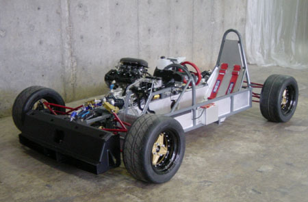
Well, unfortunately, this is only good for one axis!! and my sliding vise is only good for one axis as well. Stacking up these individually designed angle mounts and translational slides makes pretty quickly for a large, unwieldy clamping system. Well, with some creative designing and a little more forethought, a tight, stiff, compact angle vise and translational mount could be made. With a little more forethought, I could build a mill around this, and make sure all my later machining equipment use the same principles... SO this where my long term goals yet again get in the way of accomplishing short term tasks. As a great admirer of Ayn Rand, I’ve found one of her most profound sentiments to have been the clear distinction between range of the moment short term actions, and focusing on large overarching long term goals. She summarized it “The better the mind, the longer the range” a sentiment I took an instant appreciation to and have worked hard at integrating fully into my plans and goals. In working on my house, for instance, taking some extra time to clearly identify what I eventually want as my long term goal, then I can be sure every step of the way I’m going in the right direction. Obvious of course, but knowing, for instance, that I want to get laundry hookups to the upstairs apt, doing plumbing now in a different part of the house it makes sense to add the pipes I’ll need down the road for that room. Not only do you ensure that you don’t take steps backwards that will later need to be corrected (taking back down a wall to put a pipe in) taking that little extra time now might save you a lot down the road but you are closer to that end goal by the time you start on that part of the project. In the case of my aluminum casting kiln, I’m not going to just make a new kiln, but make a kiln I can modify easily into a larger or smaller kiln, or a kiln with a small addition which can have the atmosphere controlled, and a kiln that will be conducive the very large castings that I will need to do for my single sided swing arm. Similarly, every important salient aspect of my bike design has a secondary plan, some a tertiary plan, the motorcycle project itself is a positive step toward a larger, over arching goal. So this is not just about designing a vise clamp, but understanding milling machines in principle, and in the long term creating a more modular and flexible machining system. I spent a few days designing this system and researching milling machines in general - holding up the progress on my bike. It’s not just a question milling machine capability, but the concept of spending extra time initially on tasks related to designing and building this bike, for the sake of long term benefits. But in this case, and in too many other scenarios, I spend far too much time laying too large of a foundation for future projects, works, and goals, and not focusing enough on the immediate salient tasks. Sure this might make things easier down the line, but it makes them harder now! No wonder this project is taking so long! So after much deliberation I think the planning for long term goals is something that ought to be subjected to an Aristotlean golden mean as well, a critical component of a healthy fulfilling life. Something approached a little more intelligently and strategically than I was doing so. Setbacks, both in time and money, after this first major project has been completed, will be much easier to deal with. With that in mind I am seriously adjusting my prioritization, focus and efforts away from long range goals and advantages to primarily to the most immediate and rapid completion of this bike project. The only long range work beyond what has been done all ready will be only what is absolutely necessary. First question then is, what to do about custom parts and machining?? I could certainly have every custom part machined off site for these prototypes and my final version much faster than it would take me to learn milling and make them myself. One of the project builders I followed approached his build this way http://www.dpcars.net/dp1b.htm
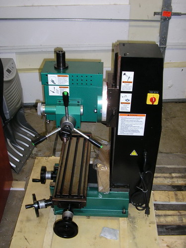
Designing from the ground up a small single seat high performance sports car powered by a Hayabusa engine, he sent virtually every component out for fabrication and assembled the components. I could certainly go this route, but see two major disadvantages with it. First, it’s extremely expensive, a custom machined part could run me a few hundred dollars. I might need 20 or 30 for this project, and for the price of 2 or 3 custom parts I can buy a milling machine. Additionally, minor errors on part design could be easily corrected with my own equipment, but would essentially require another expensive modification to the part. Most importantly, after deep consideration, the knowledge of making and refining parts correctly will have rapid and significant impact on the short term completion of the project. So of all the long term goal related tasks, I am acquiescing only to the machining / milling equipment, and probably some aspects of my kiln design. Case closed! So onto the milling machine!! The winner is the Grizzly Industrial 17" Mill / Drill. It was a close toss up between the square column dovertail mill of similiar price, I think the square columns have a lot going for them in stiffness, but the rotational swing of the head on the round column mills gives alot of flexibility. Given the cast aluminum I'll be mostly machining, I think this mill, in combination with the lathe I all ready have, should now be sufficient to make any of the parts for my two prototype motorcycles. At over 500lbs I'll need to build a special workbench for the mill. The mill is now on it's way... --------- Ok, unfortunately (or fortunately) the G3358 is out of stock, and won't be in until March! I also read a bad review of the that mill, so I went ahead and upgraded to the G0619 which I found a few glowing reviews of.
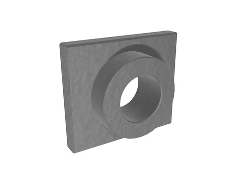
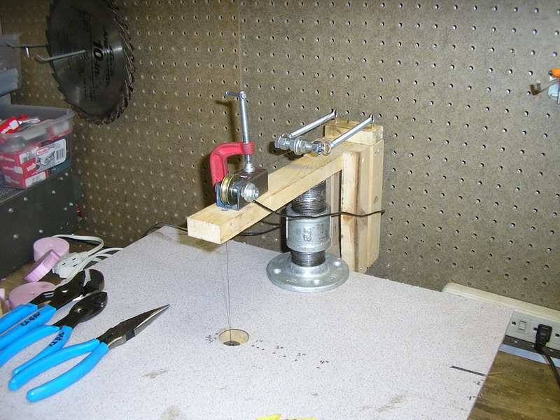
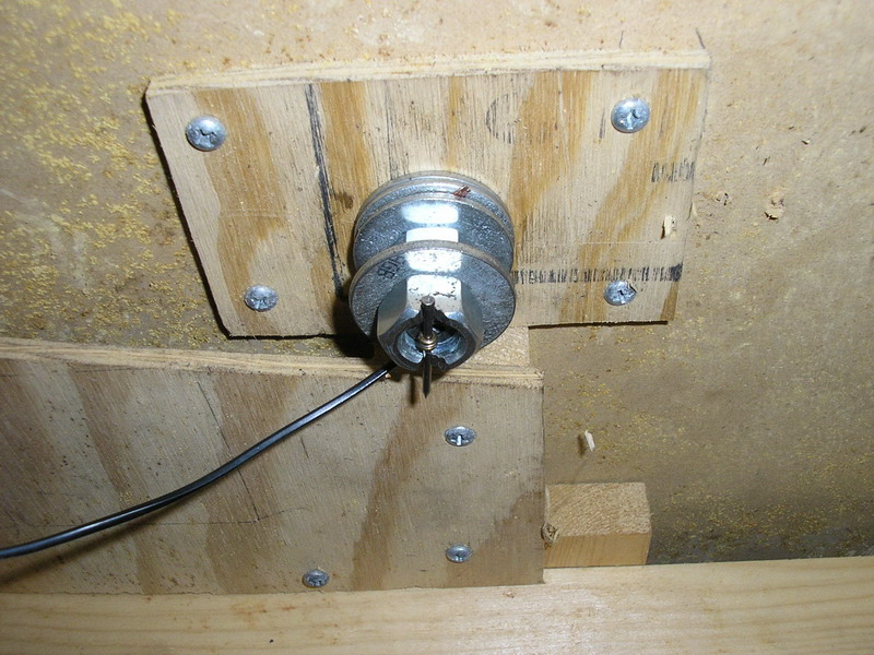
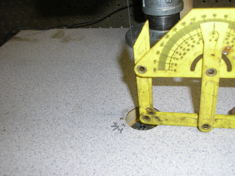
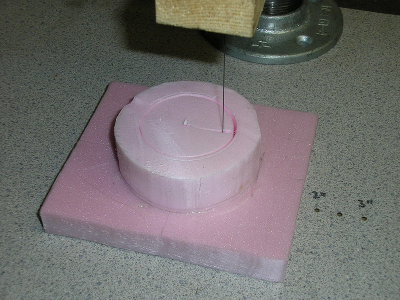
So back to the bike, here is the spindle mount I was making for the rear frame I would need to cut this part out of foam and the cast them out of aluminum, I've been having accuracy issued with my hot wire foam cutter though, and also wanted to add a mechanism which would enable me to rapidly refeed the wire. I would need to do this in order to cut holes out of the centers of parts. After the modifications... Above you see the red clamp, under that is a small pully. The hot wire runs over the side of the pully and down through the wood arm. Loosening the clamp I could slide the pully around, this made of a quick and easy way to adjust the wire with respect to the table surface to make sure it was perpinduicular. Also behind the clamp you can see two springs, these are pulling a bolt backwards. The bolt is a threaded rod with a hole drilled through. With nuts and washers, all I need to do is loosen the nuts and stick the wire through, then just tighten the nuts by hand. With this I can easily snake the wire up through a foam part. On the underside A notched nut holds a nail which is threaded through the eye of the wire (these wires are guitar strings - which work great for hot wire foam cutters) the electrical current goes to bolt independant of the nail again making it quick and easy to change. A nice right angle wire!
So, FINALLY, on to some parts! Here is one of the mounting brackets being cut with the foam cutter.
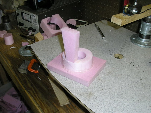
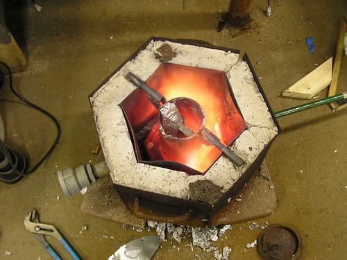
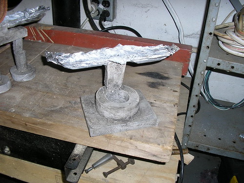
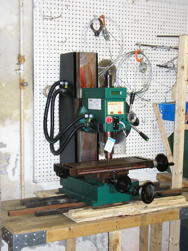
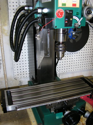
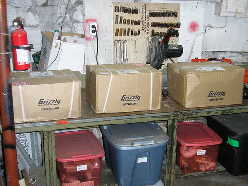
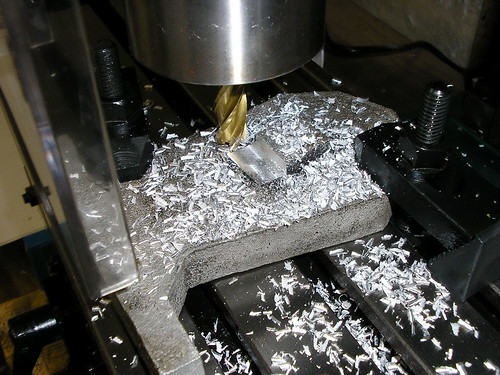
And the foam version ready for casting, my new hot wire foam cutter modifications made this a million times easier. The kiln in action I'd like to get a picture of the actual pour of the molten aluminum, but since I'm doing the pouring it's difficult, even with the timer on the camera. And the result! came out excellent! And look what came in! Transferred to my work bench via hydraulic lift through a very complicated procedeure. cleaned, bolted to the table and ready for action The accessories, it's like christmas all over again... And finally here is the Mill in action, showing what mill's are good for. The work piece is clamped to the table, and the tool is a 4 flute "End Mill" like a drill be but flat at the end and steeper spirals, it can cut sideways just as well as it can plunge cut. It worked great, this is a good quality machine and I think I'll be very happy with it. Here, again, is that rear assemply
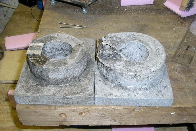
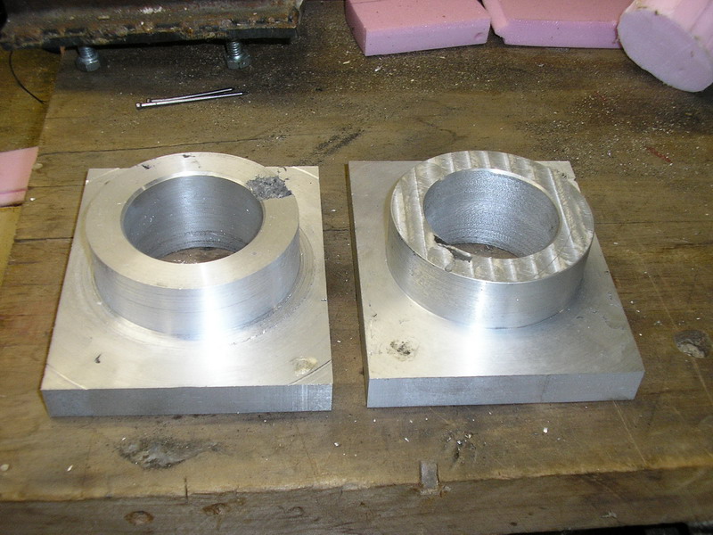
With all of my designs, I like to actually animate their assembly so I can be sure that no parts will get in each others ways, also the animations come out looking great. Here is the assembly of the rear of the bike. Back to the spindle brackets. Here are the two cast brackets
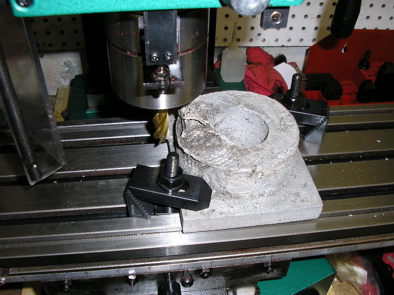
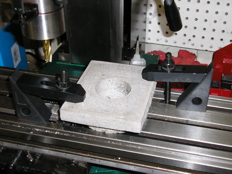
Clamped to the MILLING MACHINE!
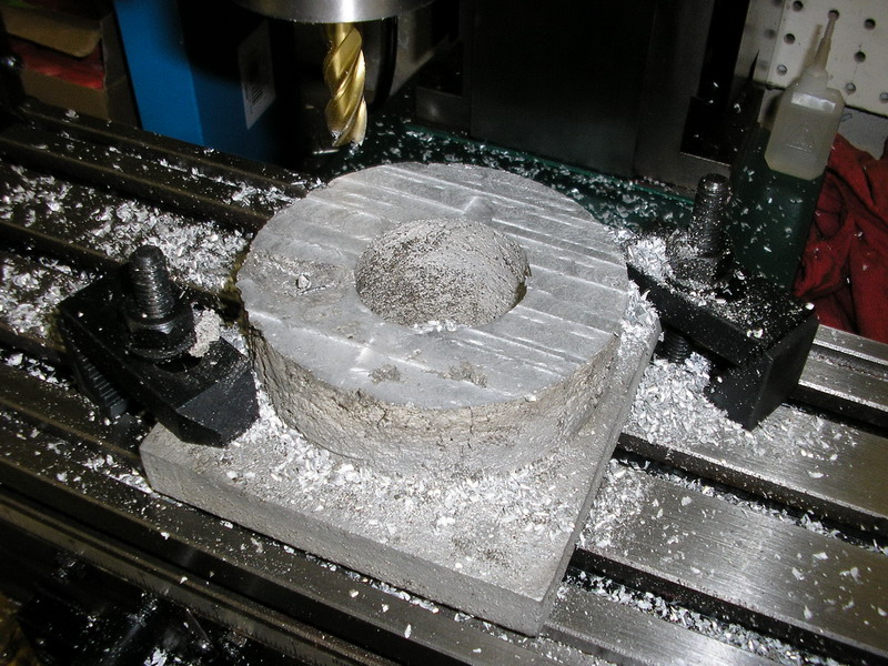
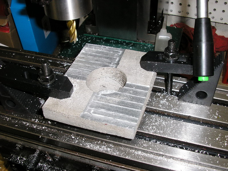
Top surfaced machined. Nice and smooth... Flipping it over and clamping it down Half of the back side machined
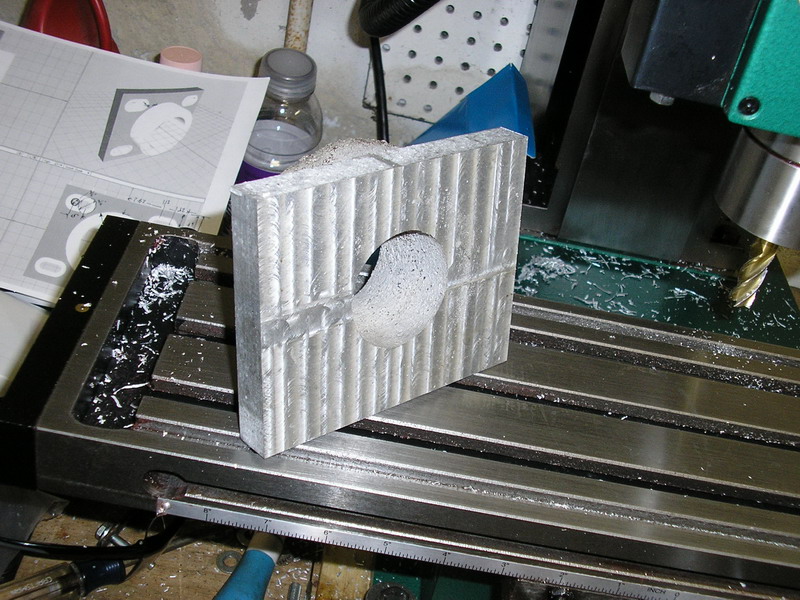
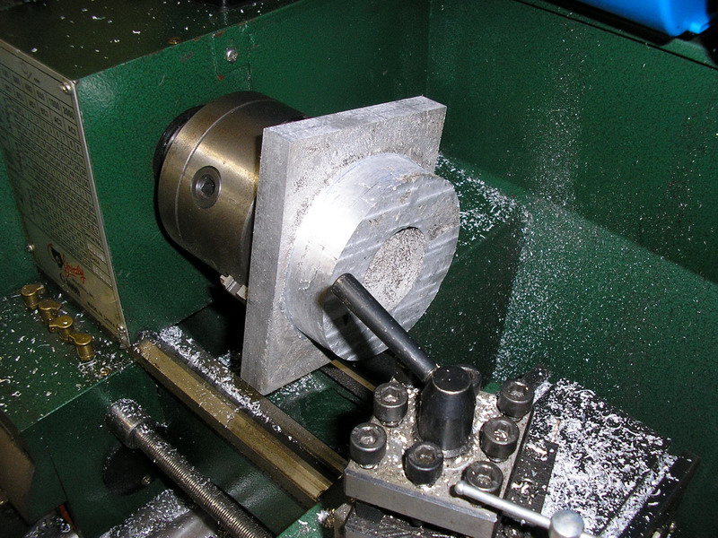
The whole thing done, front, back, and sides are machined nice and smooth. Now just have to do the curved sections on the lathe
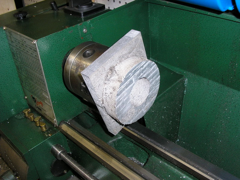
Mounted to the lathe Outside smoothed out on the lathe. The lathe does this by sliding a small triangular tooth along the edge while the part is rotating, cutting thin layer off. A milling machine, by contrast, spins the cutting tool and moves it into the part.
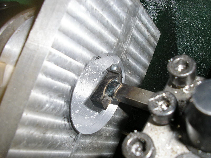
Next was the inside of the mounting bracket Actually I lacked the appropriate tool I needed for this cut on the inside of a small diameter part. So I just welded one up real quick, not too bad for about 15 minutes. In this picture you can clearly see the successive layers getting scraped away as the triangular cutting tools is moved forward into the part.
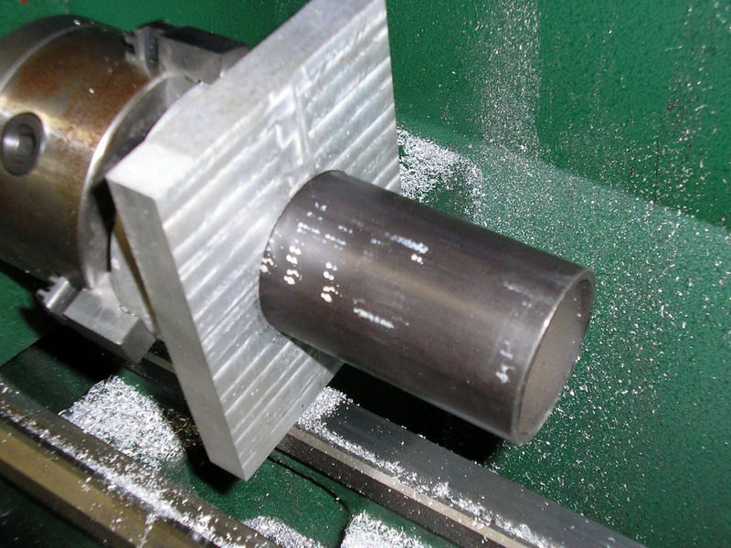
Done! just to be sure I took the part which will be the spindle and inserted it into the bracket and it fit great.
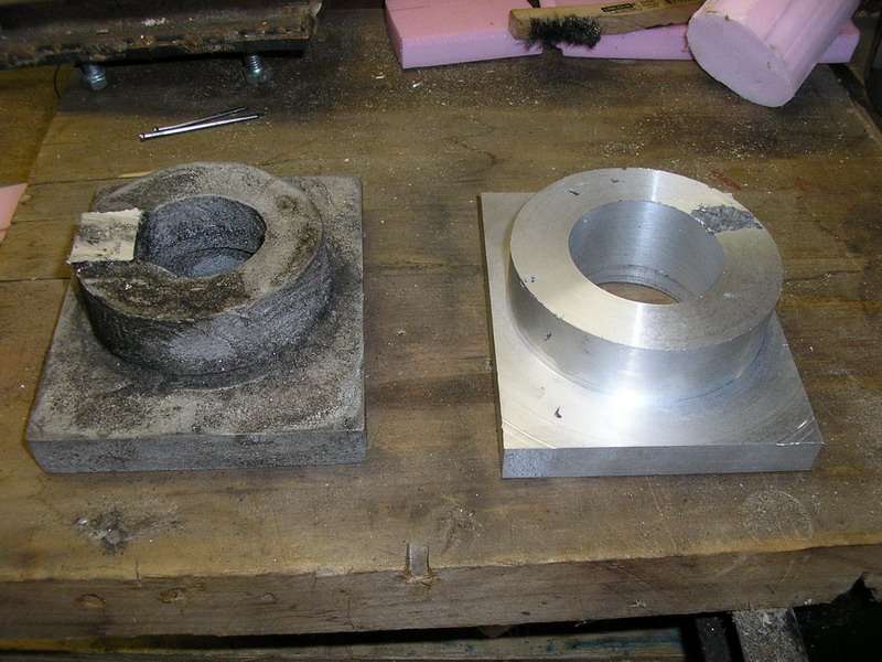
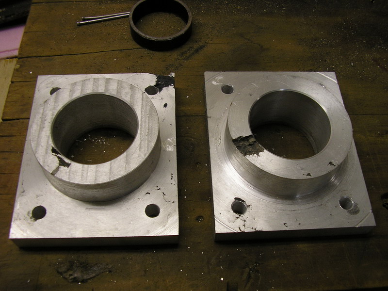
Here is the other bracket, not yet machined, next to the new one after machining, what a difference! This part came out great
A little while later, the next one is done.
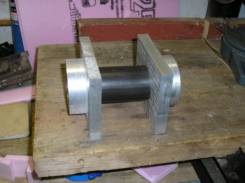
Making sure they both fit together with a section the spindle (the actual spindle will be about 2' long)
With a small section of the the spindle inserted to make sure they stay lined up, I clamped them tightly together and then clamped the pair to the milling machine. This would ensure both parts matched exactly and then I drilled the mounting holes
And that's it for the brackets! Beautiful!
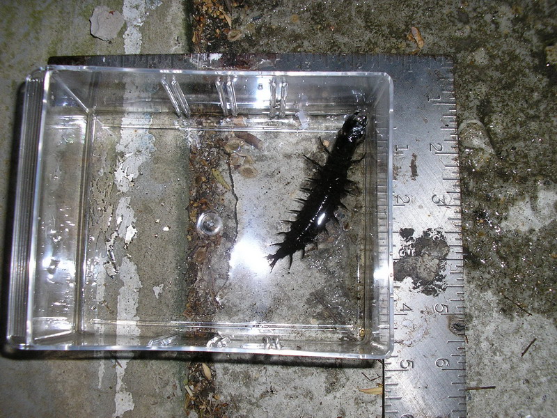
You can see some surface defects here though, as a result of my casting process. These defects do not extend into the part more than a 1/100 of an inch or so, and these parts are way over engineered. Since these parts were made I toured a real aluminum casting foudry nearbye and learned alot of great new tricks. Around this time I had a little visitor to my workshop
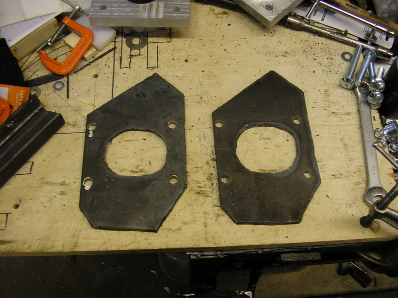
Yes, that thing is over 3" long! freaky thing. It's called a Hellgrammite, my brother who fishes knew exactly what it was and informed me. It's the larvae stage of a giant fly, called the Dobson fly, and in this stage it is an aquatic insect. Every few years they all come out of the streams and turn into the fly, for just a few days, mate, lay eggs in the stream, then die. The flies can get up to 5 inches long. From the web, though they look nasty with those giant pinchers, apparently only the males have them and they just use them for holding down the females for mating. Anyway...On to the next part of the rear hard tail mount, the steel plates that the spindle mounting brackets will bolt to. After lots of plasma torching, grinding, and drilling, the result...
Still needs some work, but on to the rest of the frame. Lots of cutting, careful alinging, and tackwelding later Last piece added, and welds done.
And (temporarily) mounted on the bike! Things are progressing well now, and I should be getting a shop helper shortly, and I have been spending most of my time working on nothing but this project now, so expect more updates very soon and check back frequently. As always, if you want to help out there are a few things you can do, including hosting some ads for my side business if you have a web site, I'm still looking for someone to assist in a major redesign of the web site, providing technical consultion if you are skilled in metal working, machining, or composite construction, or just contributing financially. See the How can I help page I'm glad to see so many people are still so patiently following this project, thanks for all your support! - Back to Status - To Next Update - |
![]()
![]()
![]()