


![]()
![]()
![]()
![]()
![]()
![]()
![]()
![]()
![]()
![]()
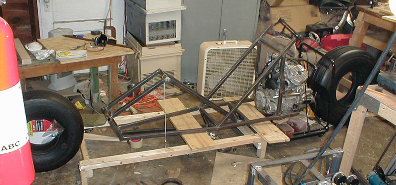
- Update 04/25/03 - It has been sometime since my last update, and many people have emailed me wondering where I have been. Well, primarily I have spent all my free time actually working on the bike in some manner, and have not spent as much time on updating the web site.
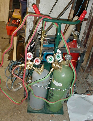
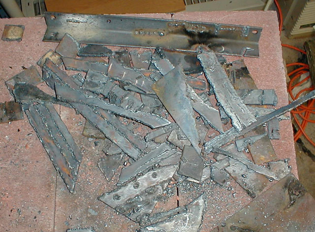
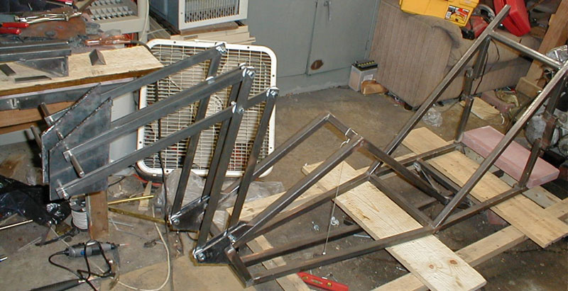
Well here is where we were as of the last update. The vehicle is roughly starting to take shape. Next in line is the front fork and its mount to the frame. First, a little about the design. In the film the vehicle is represented as having the front section, the large cowling, windshield, and handlbars as swinging up to allow the operator easy mount / dismount. After building a full scale mock up of the seat and steering system, it became apparent that such a mechanism was a necessity to the design. Without the front section raising, getting in and out of the vehicle was more cumbersome and difficult. However, this presents a few problems of its own, which I have spent months individually working on. In the prototype, I will be using a mechanism which raises the front end around an imaginary pivot point toward the front of the vehicle. Although there are a few ways to accomplish this, the method I chose was to use pairs of parrallel bars. Note, the design of the hinge represtented on the Mcfarlene toy pivots around a fixed hinge in the front of the bike, and would not be practicle on a real vehicle. The details of this virtual pivot system require accurate planning and design considerations up front, a more detailed description of this mechanism will be available at a later date. First, I had to create the brackets which mounted the VPP mechanism to the frame. This required cutting a specific shape out of a large plate of steel. So I had to learn... Torch Cutting
Hence my new purchase, an oxy acetelene torch. This ran me about $600 ready to use. Torches are usefull for brazing, cutting steel, heating metal, and welding Aluminum, Steel, and other metals the basic Mig welder will not.
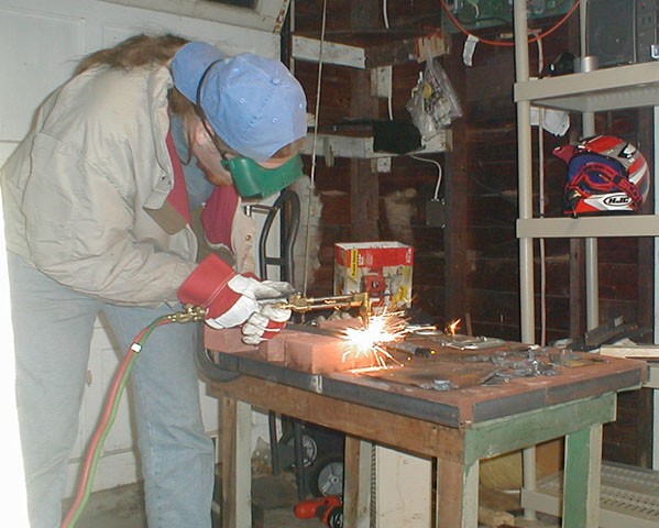
At work with the torch.
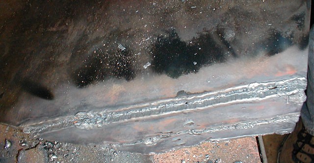
My first cuts, 1/4" mild steel plate. Not so good...
The culmination of practice cuts. It takes a steady hand and a slow speed to cut well with an Oxy Acetelene torch. It took me a few weeks to get a consistently decent with the torch. Virtual Pivot Point Frame Mounting Brackets
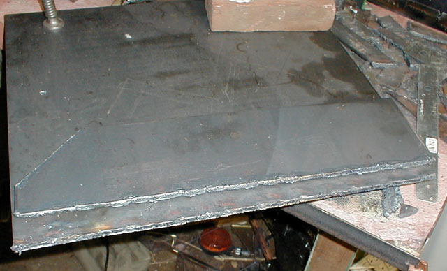
Getting ready to cut the mounting brackets out. This large peice will be cut into smaller pieces.
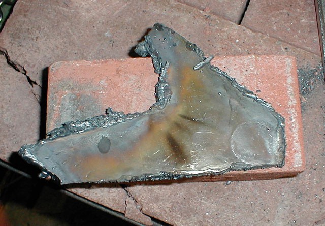
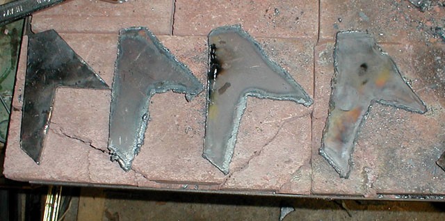
The first piece cut out. Note lots of slag.
After some grinding.
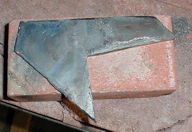
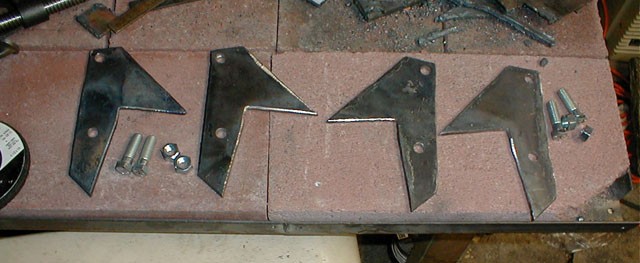
The remaining three cut out, some better than others.
After lots of grinding. One piece is beveled, ready to be welded to the frame.
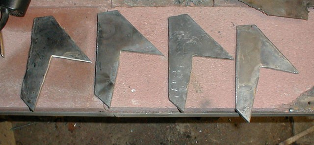
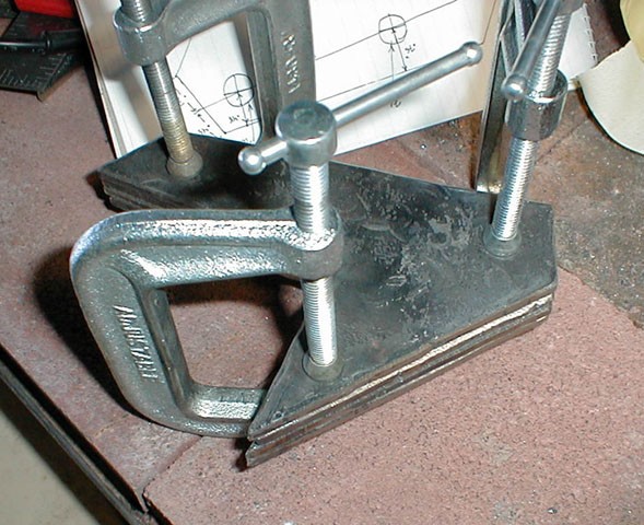
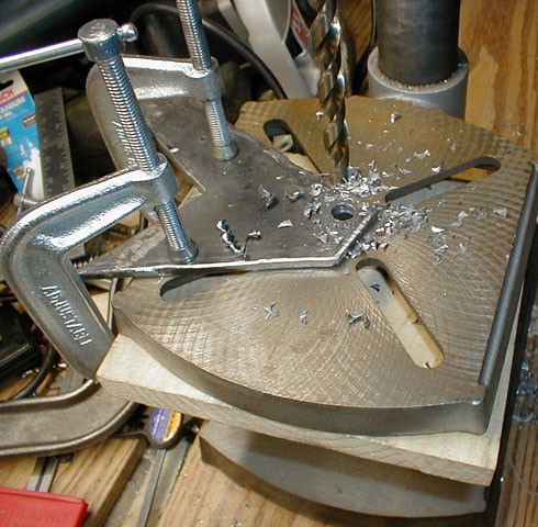
The four brackets clamped together, ready to be evenly grinded and have pilot holes drilled.
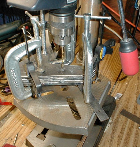
Pilot holes being drilled.
Drilling the 7/16" bolt hole through the pilot hole.
All of the holes now drilled.
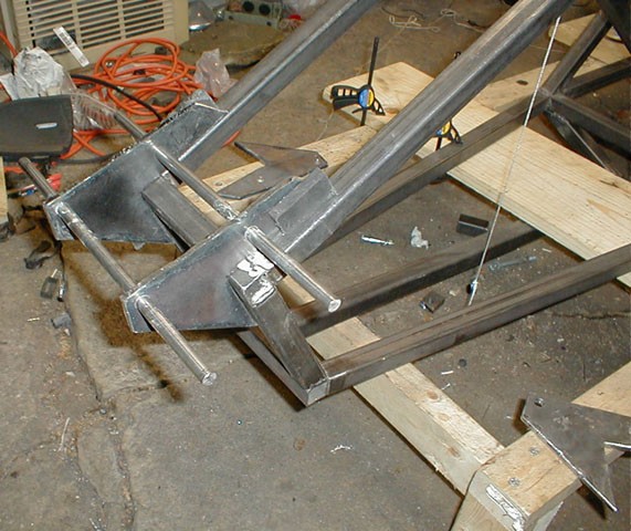
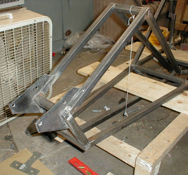
Placing the brackets with rods on the frame . Here is the assembly comparing the level of the VPP rods and the level of the frame. After adjustment, which took some time, the two were not visually distinguishable. The brackets are held to the frame with some strong ceramic magnets.
After careful setup, the mounting brackets are tack welded to the frame front.
This is the weather I was out working in.
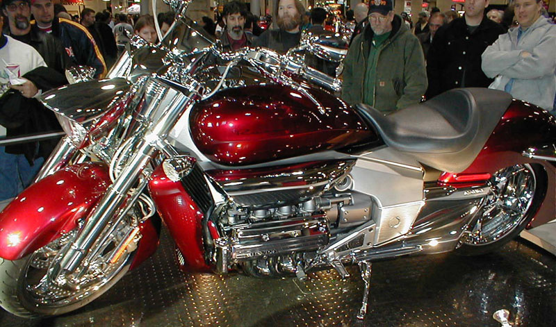
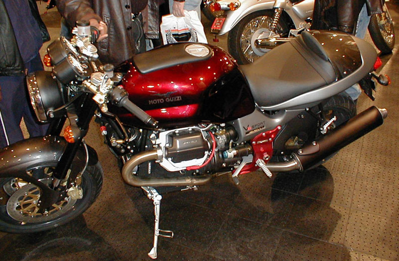
Ill take a moment to show some pictures from the New York City Cycle show I attended about this time in the building process. Here are my two favorite vehicles of the show, The Honda Rune, shown above, and a fine MotoGuzzi shown below. Note the pronounced trailing link front suspension on the Rune.
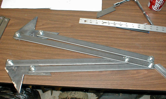
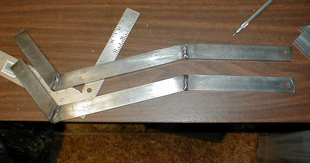
Virtual Pivot Point bars
The VPP bars consist, at the moment, of 8 bars total, 4 with two holes, and 4 with three holes. Here is the first pair. Made from hot rolled 1/4" x 1" mild steel.
The other pair made, and mounted in two opposing brackets to demonstrate the principle.
Here is the same thing, opened up. Note, this is opening much farther than it will on the vehicle, which will be more like 30° - 40°.
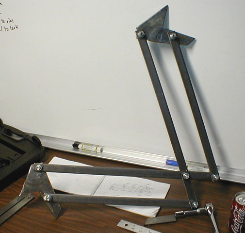
The virtual pivot point bars went through a few redesigns, along with the fork and steering column. Initially, they were to look like the peice above. The total length from one end to the other was identical tothe counterpart bar above, the bend in the bar went around the Fork T's when they were turned. Some further work on this design revealed some simpler ways to accomplish that, and so happened to make the overall fork design, which youll see in a later update, be 1) easier to build 2) safer 3) look more like the actual fork is presented in the schematics and drawings of the Akira vehicle. The entire VPP bar assembly was subsequently remade with cold rolled 1/4" x 1" bars and required no bends or welds.
Here are the two pieces, which were subsequently replaced by straight cold rolled bars.
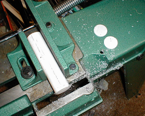
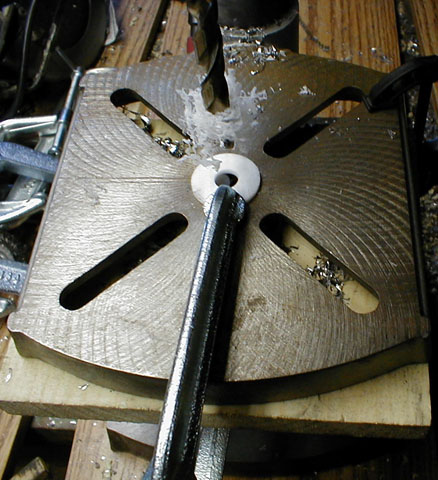
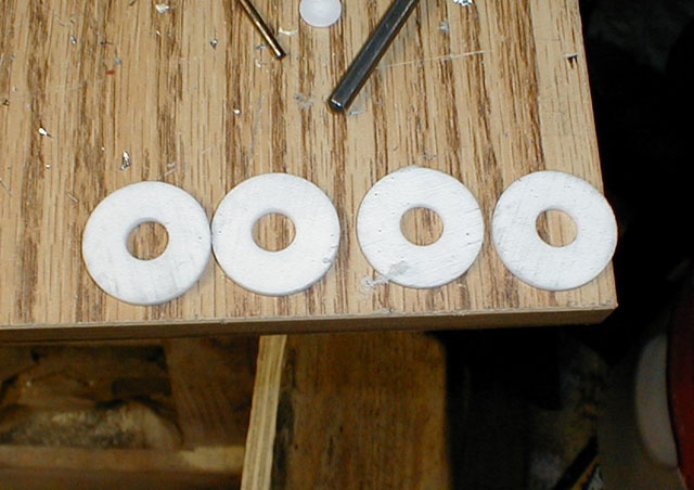
The VPP parrallel bars will be bolted sandwiched between the mounting brackets on the frame. The question arises how to allow them to pivot freely yet be held securely in place. Typically thrust bearings would be used in an application such as this, but for the purposes of this prototype I settled on a low friction plastic, aka Teflon (PTFE) I bought a stock bar of it and slice off 1/8" spacers which are then bolted between the VPP bars and the brackets. Note, this is only for the prototype, this will be replaced with sealed thrust bearings.
Drilling the washer / spacers / bearings
Ready to be used.
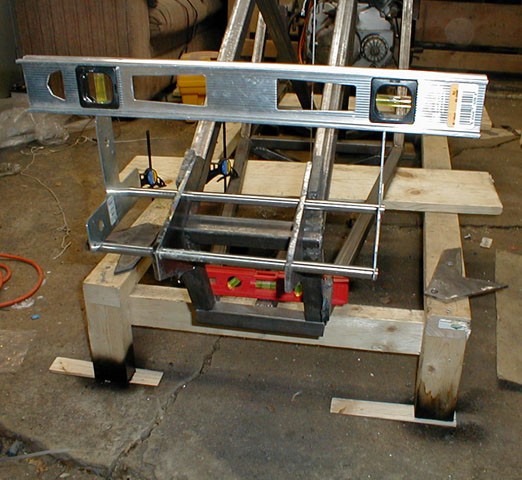
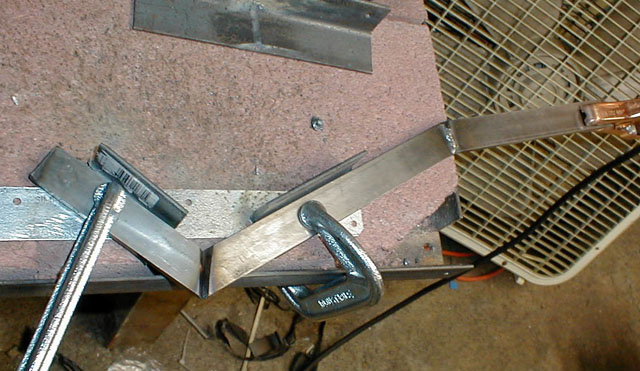
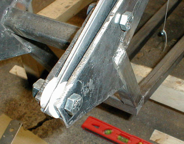
Here is one of the bars, and spacers, bolted between the brackets on the front of the vehicle. Note the outer bracket is not yet welded.
Here is the left half of the assembly opened approx. 35°
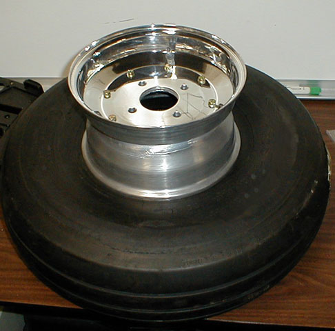
Here is the front Wheel and Tire. Note, a few people have emailed me asking me what I am using for tires. As with other technical questions, I will not be revealing the specifics of the technical design until after the prototype is completed. Primarily because I do not want people copying an idea that may prove fatal. Let me verify that all this works first, and then I will be more than happy to provide detailed plans and technical info.
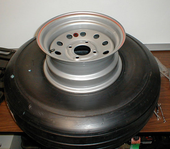
The rear wheel and tire.
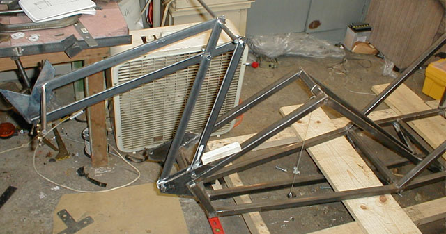
The completed front VPP and bracket assembly, also included are the steering column housing mount brackets, not yet complete as of this image. See the next update for the steering column housing. Keep checking back for updates.. Matus - Back to Status - To Next Update - |
![]()
![]()
![]()