Update 01/25/04
This is a big update, so give it a few minutes to load...
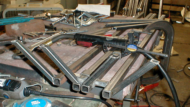
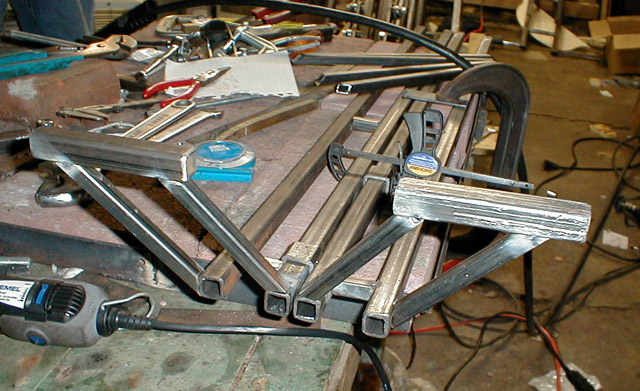
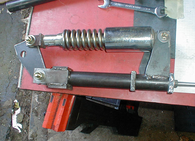
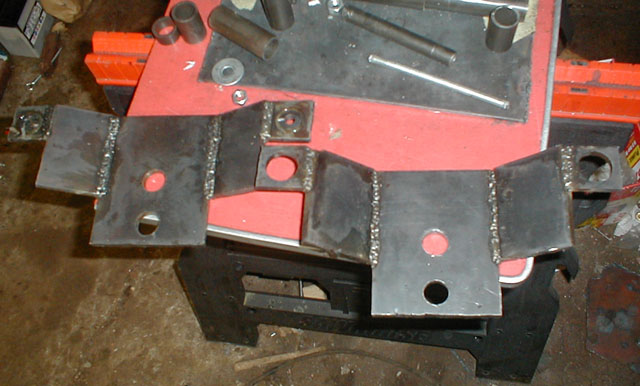
1st up, the foot rests
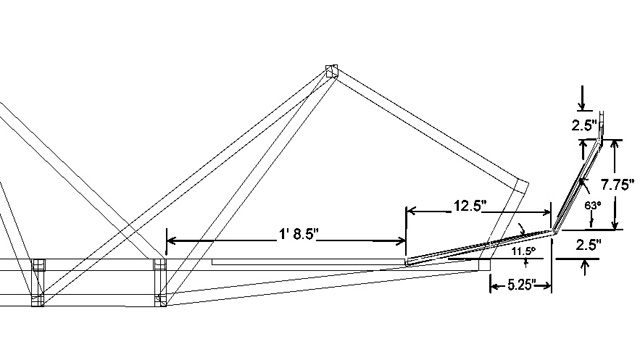
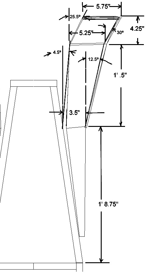
These previous two images show the dimensions of the foot rests.
The foot rests under went some redesign since the original designs and even since the images above. I decided to make the foot rests constructed of two parrallel bars closely spaced that could easily slide in and out (forward and back) to accomodate taller or shorter operators.
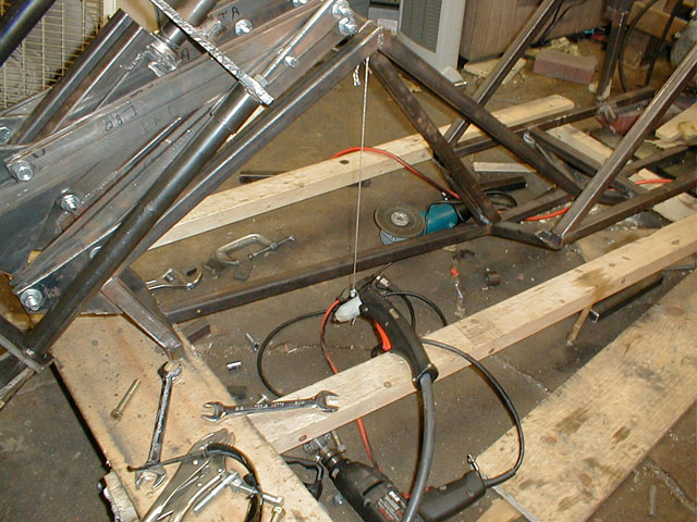
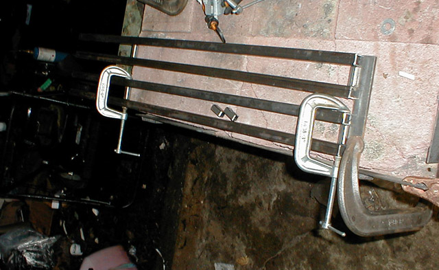
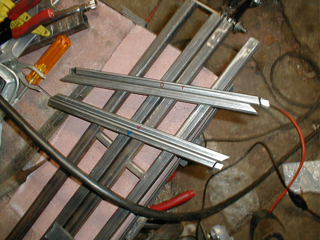
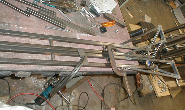
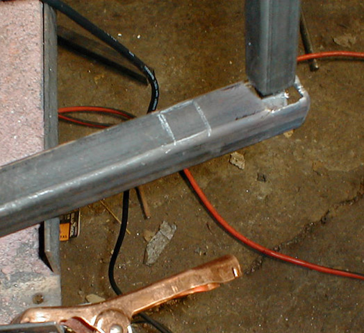
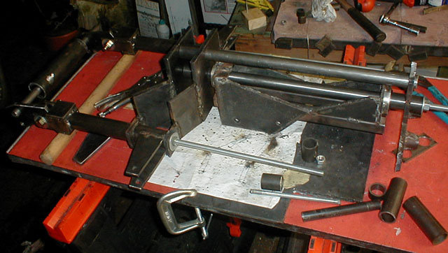
Here the bottom two bars are removed from the frame. The plasma torch turned out to be a great tool for 'unwelding' things.
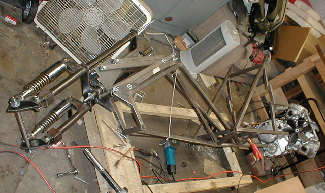
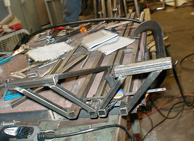
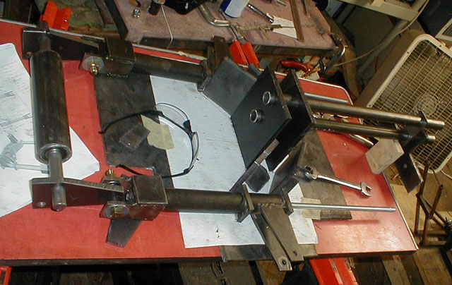
The frame turned on its side to facilitate removal of the bottom beams. They will be replaced by two straight beams. Note the assembled virtual pivot point section holding the steering column in place, with the fork mounted and turned 45degrees.
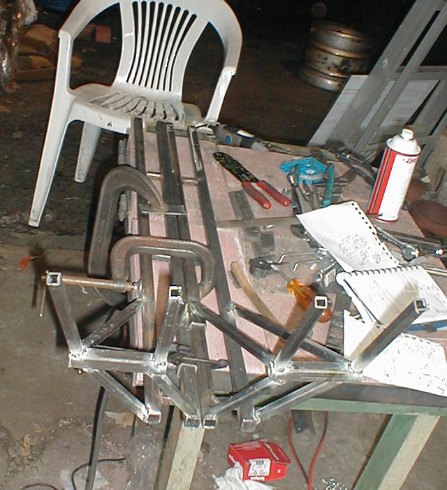
The construction of the foot rests begins. Here you see the two pairs of parrallel bars, these are made of 3/4" mild steel tubing.
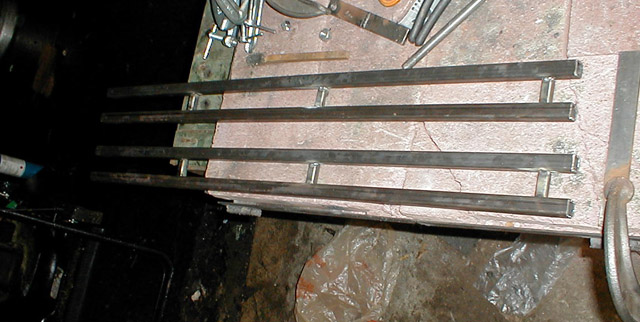
The cross members are welded in place, these are made of 1/2" mild steel square tubing.
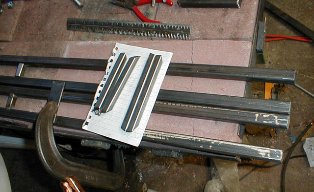
Now the actual foot rests are being cut and readied for welding to the parrallel bars.
The first two pieces tack welded
The first four pieces now done. Note the spacers made of 1" thick walled (3/16") mild steel tubing around the 3/4" tubing. These pieces will serve as the attatchment to the frame for the forward part of the foot rests while still allowing them to slide longitudinally.
The next two pieces welded on. These are back to 3/4" tubing.|
The next few peices waiting to go.
Now here they are welded to the 3/4" cross pieces and back down to the parrallel bars.
Both sides down, not from a different view.
Here the next four pieces are welding on, waiting only for the last two.
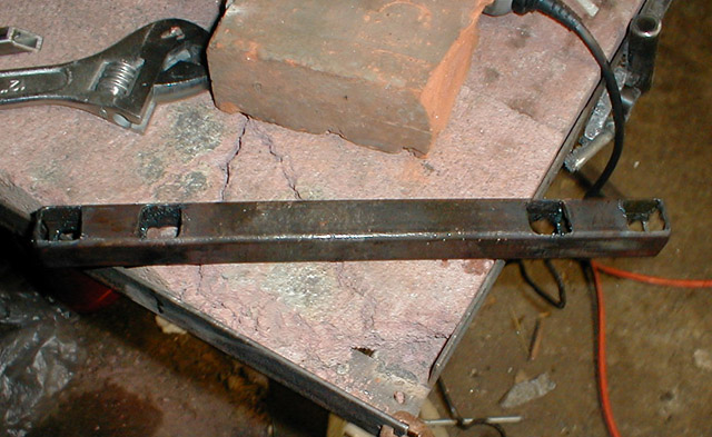
The completed basic foot rest assembly.
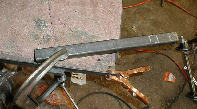
Here the new cross member is planned out. Where the white squares are will be cut with the plasma torch, this will be the opening in the frame that will allow the foot rest parrallel bars to slide forward and back.
The first part cut out.
Here all the cutting is complete on the new cross member to the frame.
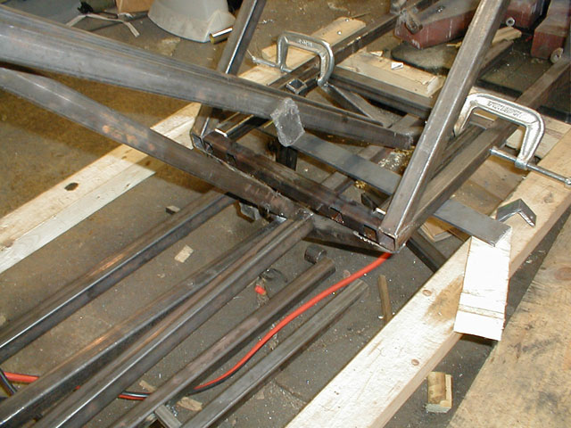
Here the new part is inserted where the old one was removed from. Note, it would be better to have the foot rests outer parralell bar slide right into the longutidunal frame support on the outer sides (not the opening at the end of those 1" tubes right next to the outer square of the new member) Those tubes however are the thinner walled 1" square, as opposed to the thick walled ones that fit perfectly around the 3/4" tubes. This is an example of something that I will take into account when designing the final version of the bike and rebuilding it.
Here the parrelel bars are inserted into the new cross member of the frame. (This was before the foot rests were welded to the parrallel bars)
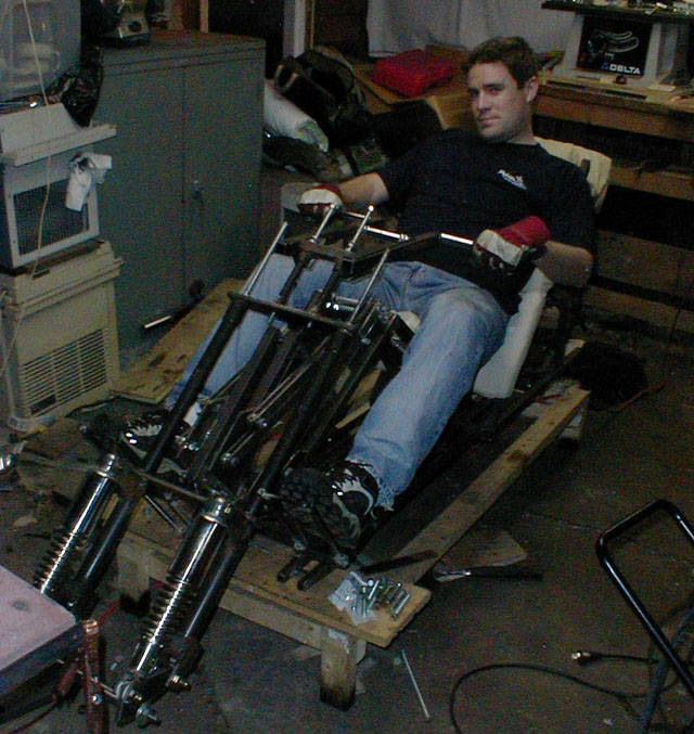
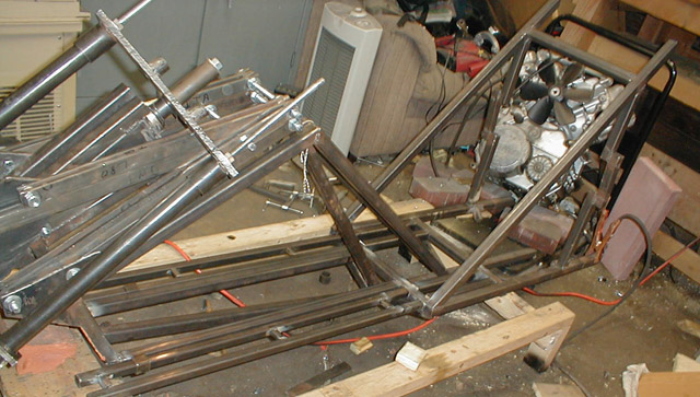
And here is my brother on the bike with the foot rests inserted. Also note the handlebars are present here, I will detail their construction later.
Well, a lot of problems arose from the previous fork design after a few design changes of the foot rests, primarily if the foot rests had to be designed to splay outward significantly to fit the the turning of the parrallel bars of the fork. After some deliberation, I decided to alter the fork design.
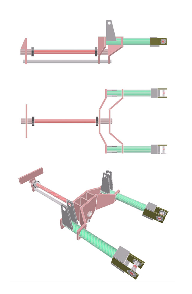
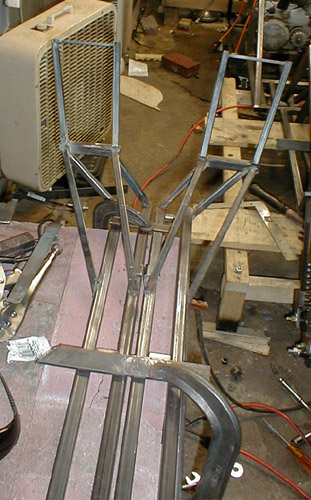
Here is the new fork design. This is merely similiar to bicycle forks, where the steering column spreads into the structural fork. I took care to make this fork mostly out of the parts of the existing fork, so only minimal extra work needed to be done. I also added a second bar that runs underneath the steering column for additional strength. I ran this through Solid Works FEA program, checking for twisting moments, bending moments and lateral flexing.
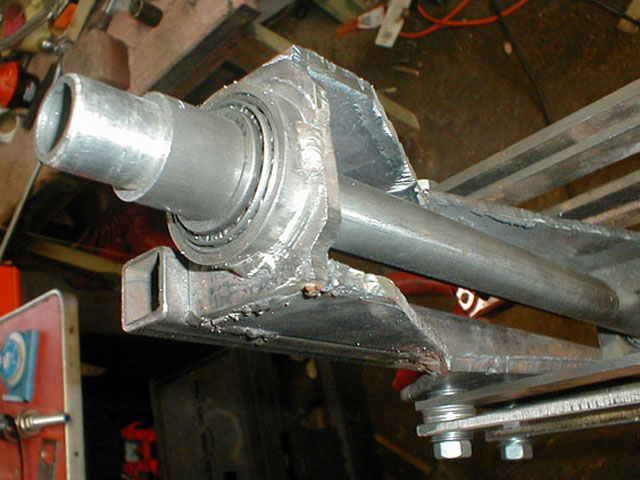
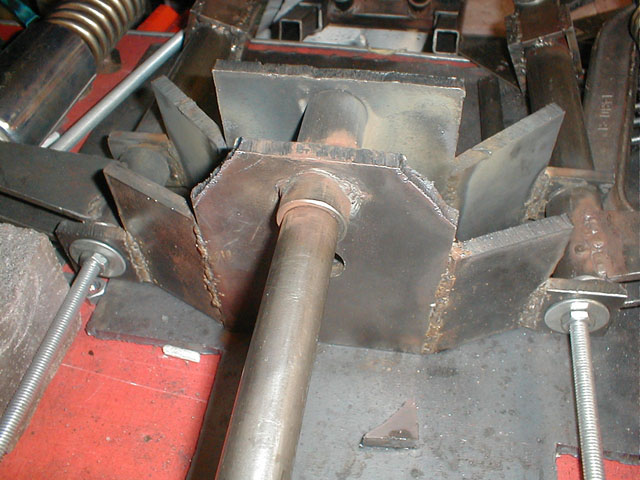
First of all, to make room for the lower bar, the steering column had to be slightly modified. The notches at the top center of this image and the center are what was cut out, this allowed the parrallel bar to turn 45 degrees and created a steering lock, preventing it from turning further.
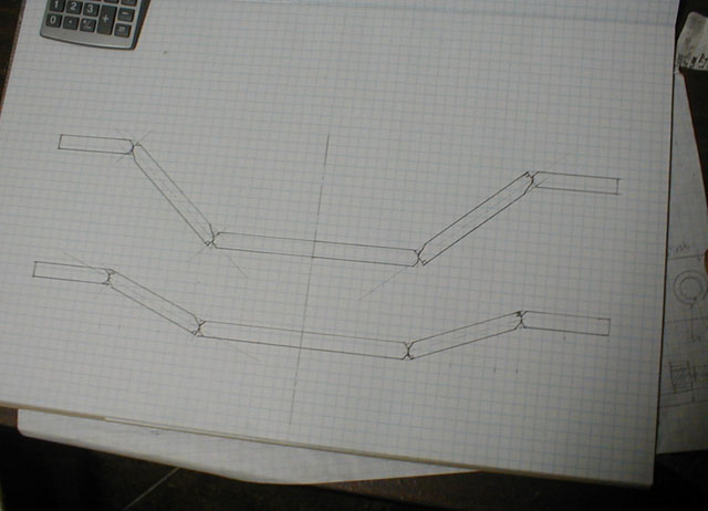
Outlining the fork segments on scale graph paper, ready to have the individual components laid out. The notches are present to allow the beveling required to get good welds.
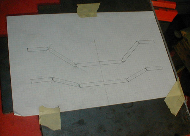
I then taped the paper to a metal base, so I could use magnets to hold the individual pieces in place to take weld.
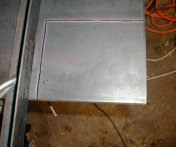
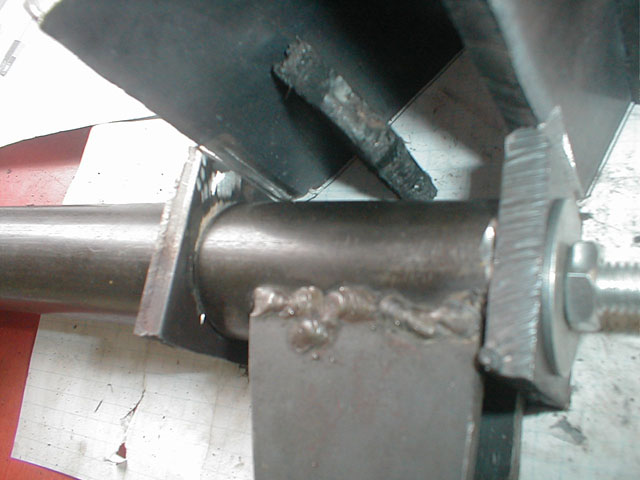
Here is the first cut for the new fork, this is through 3/8" steel and cut with my plasma torch.
Notice how good the cut is with the plasma torch compared to the old practice cuts from the Oxy-acetelene torch. (ideally this cut could be even better)
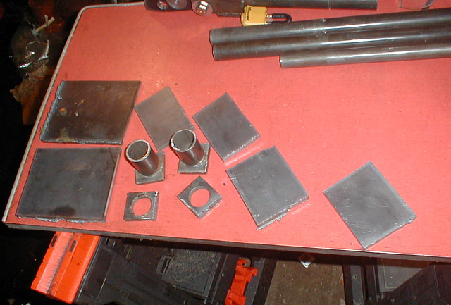
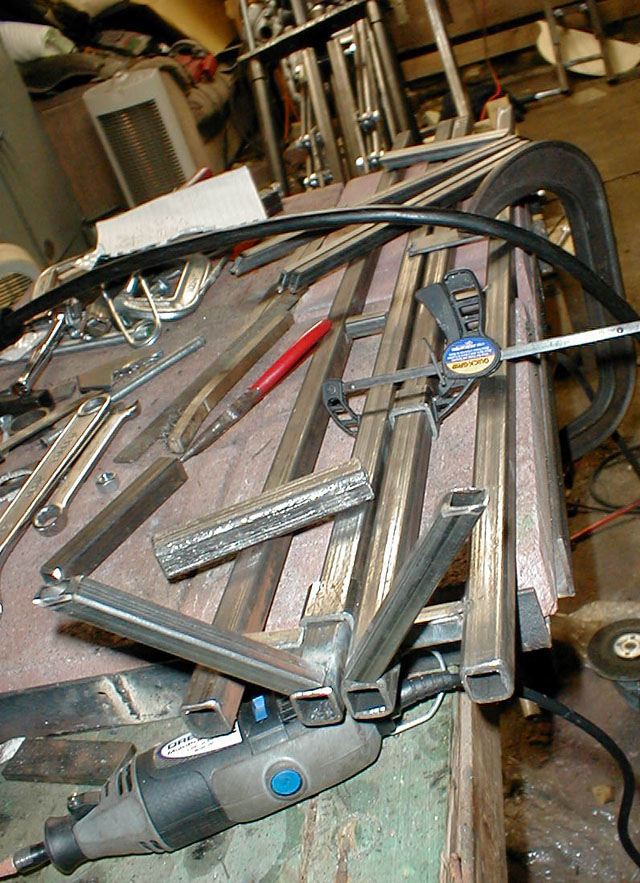
A bunch of the pieces cut and awaiting assembly.
Here is each side of the fork, the two square peices torward the base of the suspension mount that we are looking at end on are the ones that get welded to the fork T's.
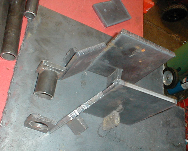
A quick mockup, here you can see where those two pieces will go, on the left side in this picture.
With the fork parrallel bars mounted and about to be welded. The piece standing upright is a magnet holding the metal in place.
Here is the full mockup, waiting to be welded.
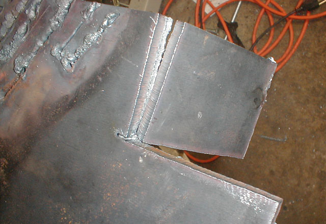
After take welding, it was dissassembled and stitch welded. Here is the front and rear fork T.
Assembled again.
The Inner plate had to be notched slightly to make room for the lower Virtuarl pivot point brackets. The original design called for them to slant up toward the lower part of the next peice anyway, instead of the steps like they are here.
The completed Fork attatched to the steering column.
Up next Wheel assembly and Handlebar assembly
- Back to Status - To Next Update -