2013 Wrap Up - Another Year of Limited Progress (scroll down for update)

Welcome again Akira Bike Project fans. I am disappointed to say that 2013 was another bad year for my Akira Bike Project, and I apologize to all the loyal followers for another year of limited progress.
I was quite excited come June 2012 to move out to Seattle and as a Production Manager and launch a new brand of bikes and getting valuable experience necessary for when I would turn around and launch my own bike. Instead, the day I arrived here in Seattle the owner informed me he wanted to close up shop. He would go back and forth on it, and it has been a frustrating roller coaster ride for me.
Contribute

Dwolla is
a cheaper, cleaner and simpler competitor to Pay Pal.
Dwolla also supports recurring payments, you just have to manually select them, they don't offer buttons for them yet. Dwolla charges less per transaction and so gets more of the money you contribute to the bike project.
Pay Pal also holds your money for 30 days.
|
|
|
|
| |
| Re-curring payments of $10, $20, $50 / month will be the most helpful to the project. See how to set them up on Dwolla here |
R.I.P Datamancer
I would like to take a moment to tell you about Richard Nagy, aka Datamancer, or "Doc" Doc approached me a few years ago as a fellow maker, inventor, and Akira Bike enthusiast. Doc was a famous artist, top notch in the Steam Punk community. We talked frequently, tossing ideas back and forth, he pulled strings and contacted friends trying to help get my project moving along as well and was always helpful to hash out technical ideas with. I always envisioned we'd embark on some grand mutual project together, and I really wanted to see him take my bike platform and make a steam punk work of art out of it, a project he was excited by. Sadly he was tragically killed in a car accident, leaving a healthy inspiring relationship with an intelligent beautiful wife behind, thousands of unfinished projects he passionately poured himself into, and legions of adoring fans. Some close friends and co-workers will continue his work. Please check it out and take a moment of silence in homage to Richard's creativity and stellar qualities, and take a moment to scowl and curse the unjustness of the universe.
Check out www.Datamancer.com
Akire Bike Project Progress
After some time at Crazy Horse, I did finally get my shop space setup. It was a little crowded, and I had no power for my welding equipment.
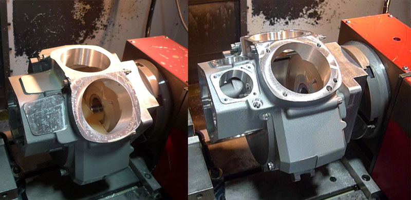
These are the motors we build, these are the engine cases, and this is a before and after of some of the 4th Axis machining operations. CNC machines can have an aribtrary number of Axis, they are not limited to the 3 you might think of in physics or cartesian co-ordinate systems. Basically like a typical axis it is any plane the machine can move along, so you have your conventional X,Y,Z axis, which is up/down, left/right, and forward/back. Basic machines are 3 Axis. In this machine we have a 4th axis installed, it is the red block on the side, it has a rotary table which the engine case is bolted to. That rotary table's rotational axis is the "4th" axis. Sometimes you will have a rotary table like this but with another rotary table attatched to it (usually though it is supported like a cradly on both sides) and that would be a 5 Axis machine. Some machine can have 7,8, or more axis.
Shortly after my arrival I took a trip down to Oklahoma City to pick up our frame Jig made by Sam Well's. I was dissappointed I didn't get to make the jig, but Sam is the best in the business.
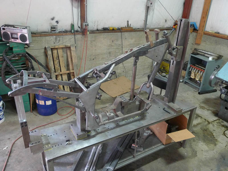
Here is our Jig with a frame in progress mounted into it. This is a good reliable jig with numerous rigid mounting points but which also allows for easily removing the entire frame after welding. A frame jig holds all frame parts in place while they are being welded together. This thing weighed probably 800 lbs.
Ok, on to actually making some bike parts
First up, I was unhappy with my front end parts and decided to remake them on the CNC, it would be a good part to learn on as well. First up, is the fixture for holding the part.
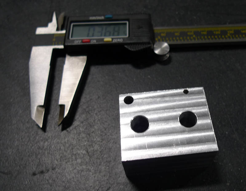
So here is an aluminum block machined square with two holes in it for bolts. The intention is to bolt the work piece to this, and then clamp this down inside a machinist jaw. It's interesting in machining that sometimes the most difficult problem is how to hold a part while you are machining it. A good machinist will keep all the fixturing in mind when designing the part, and our machinist joked that he would often get parts that it was just completely imposible to clamp it down. Sometimes it can be quite a puzzling challenge.
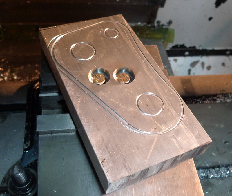
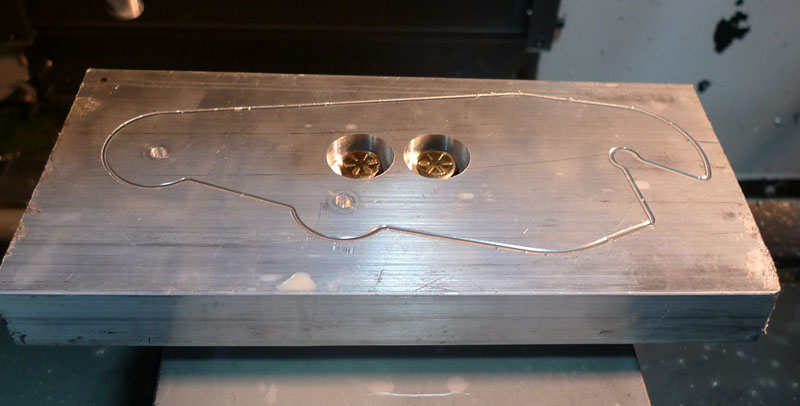
So here we see my part ready to be made. The two holes in the middle were drilled to match the holes in the other block, and then this piece is bolted down to that small block above, and that small block as clamped in this vice. A quick run was done of the outline just to make sure the part would fit. This piece is thicker than the final piece, so the messed up outline is just removed. Good thing we checked because it would not have fit. I had to make do with scrap pieces and this one just barely worked.
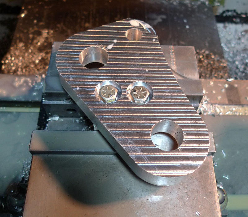
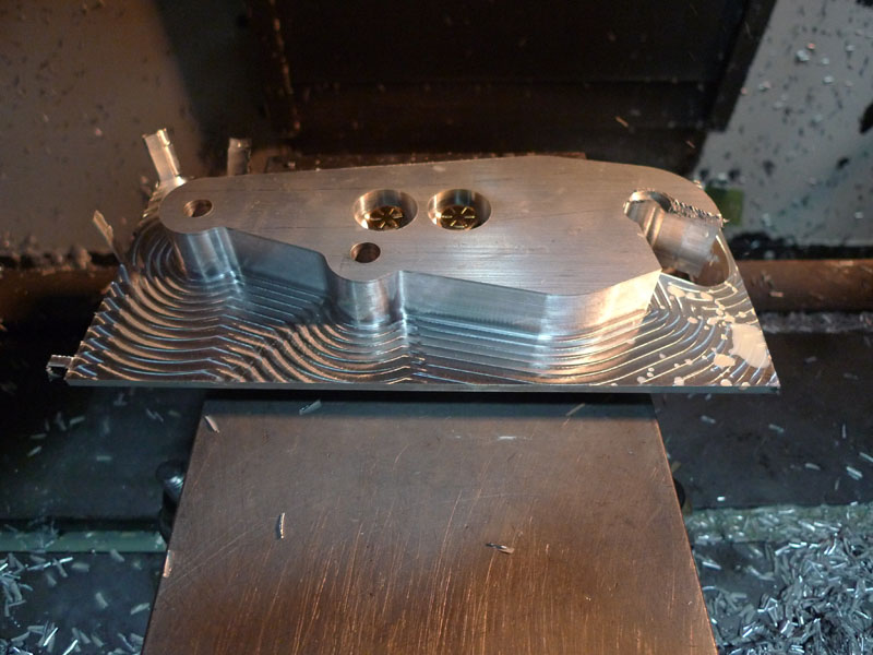
So here it is, completed. You can clearly see why it had to be held from below with a small block, because the machine cut the curved outer shape and holes all the way through the work piece, so you couldn't hold this with the vice grip from the edges. It turned out though that the piece could move a little no matter how much you tightened those bolts down. So this was a second piece and the block was remade with threaded holes instead of straght through holes. I later learned a professional would have probably made this out of one big block, and the last step you would flip it over, clamp the hole part from the sides in a negative form fitting fixture, and then mill the block off the bottom. But when you are just doing 2 parts, making complex fixtures takes more work than the part you are making.
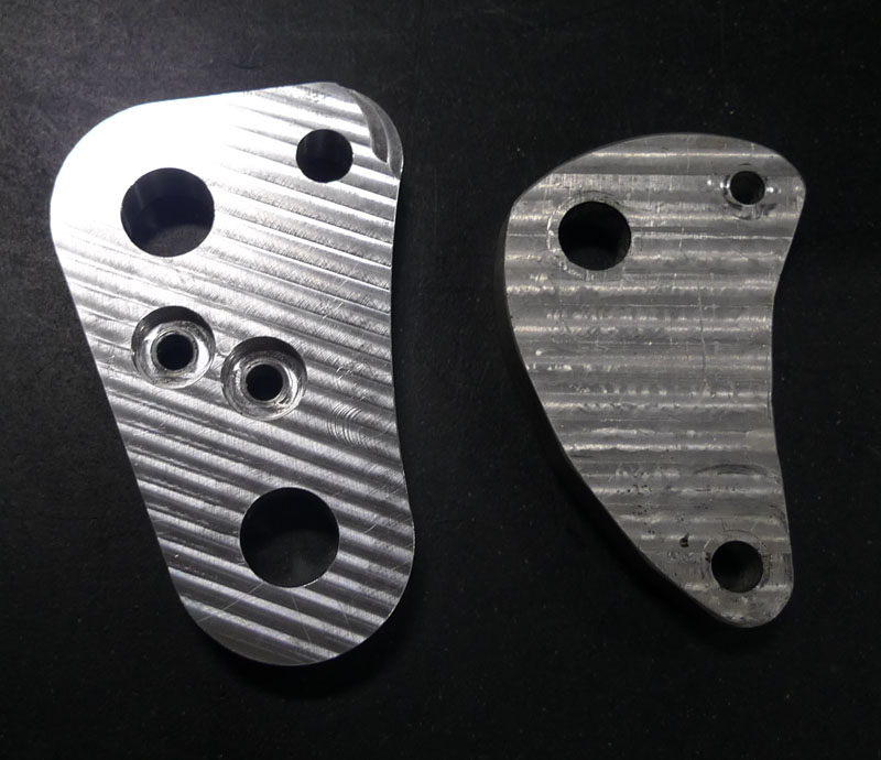
So here it is next to the original. This is the leading link. The large hole ont he bottom takes the whole weight of the front of the bike, transferred from the forks, and the large hole in the middle is the spindle, so I wanted to beef these holes up and give them enough room to also allow for bearings to be pressed in. The old leading link on the right was cast by hand by me in my kiln in a previous update, and then machined by hand without a CNC. Doing curves without a CNC is down with a rotary table. You clampt the part to the table where the center of your curve is the center of the table, and solowly rotate it. You need to do this seperately with every single curve though! Man what a pain in the ass that was. With the CNC, it's program, click, and go. Compound curves are no more difficult than straight lines.
Next was the leading link. Here it is clamped down using the same fixture block I made with the two holes. Again an ouline was machined in to make sure it fit. Looks good!
Almost done! Here I started to get concered about how thin the aluminum section was getting. Worrying these pieces could suddenly break off and go flying. Instead of milling this down from the top, the way I did, it should have been milled from the outside in. Here our machinist re-programmed it to cut the correct safer way.
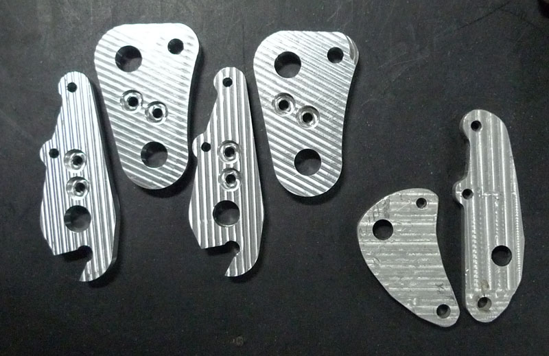
All done! Here are the two new leading links and the two new caliper mounts next to, on the right, the old leading link and old caliper mount. Honestly I stare at these sometimes I think they are quite beautiful.
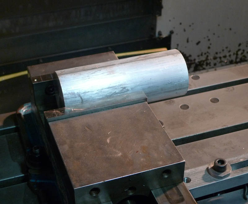
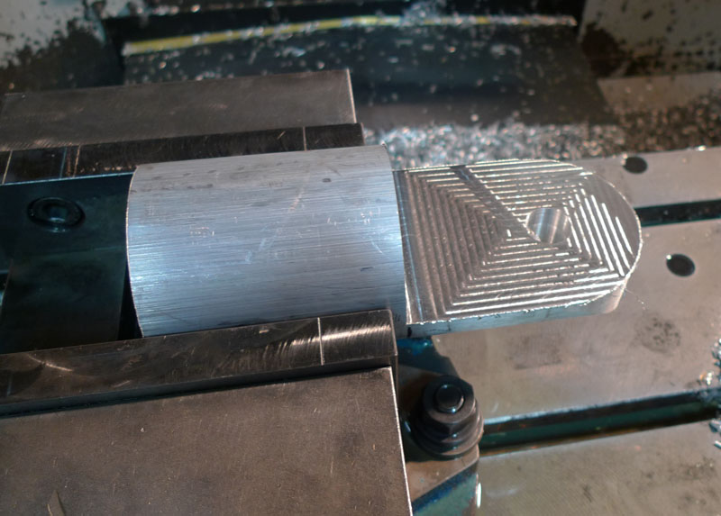
Next up was the fork ends. Again I was unhappy with the old ones, which were hand cast and of low quality. Here is a stock 3" diameter aluimnum bar cut to length and clamped in the CNC vice.
The top side is flattened how, some holes are drilled and tapped, and the rounded profile in the end is milled in.
Then the part is flipped over and the other side is done.
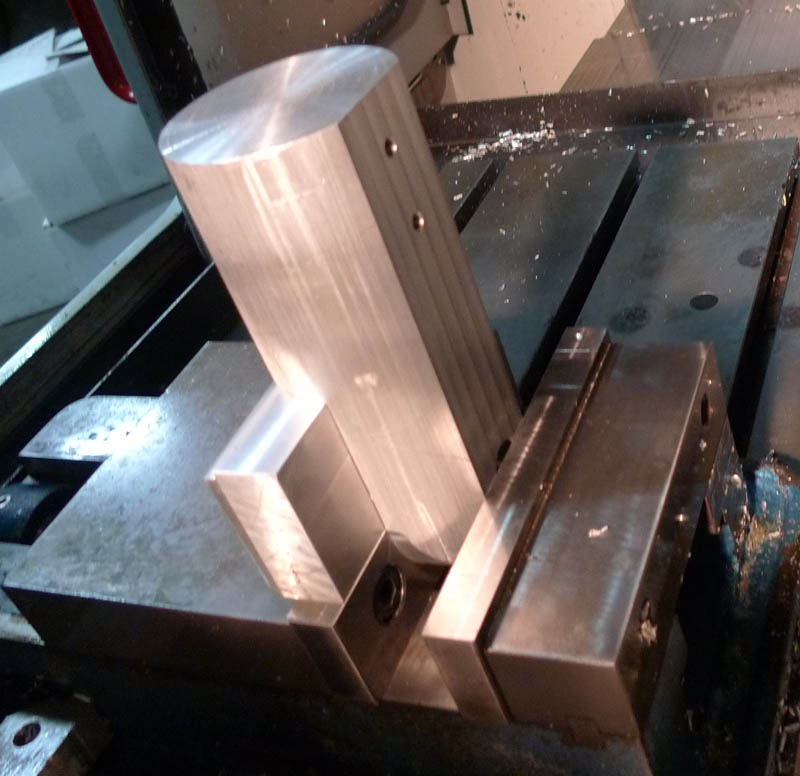
Lastly, it is stood up vertically as the hole in the end is milled in (it's not there yet)
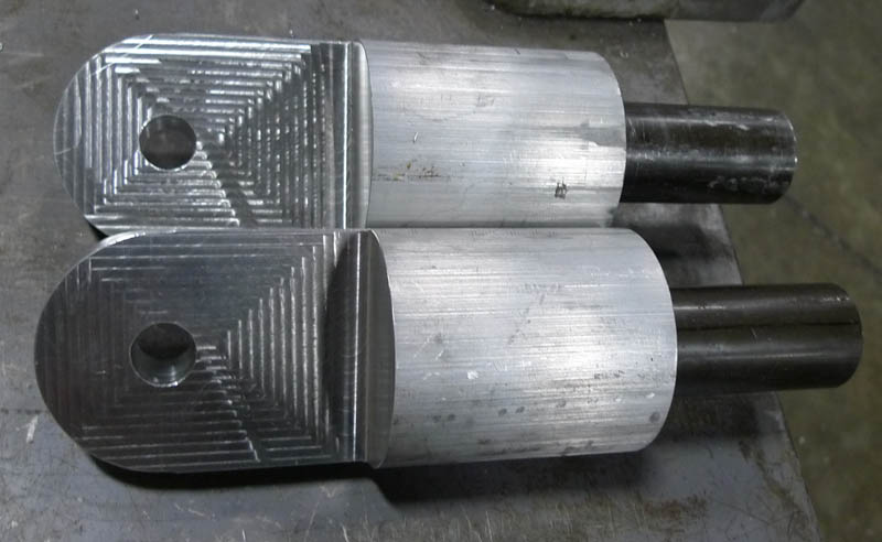
Here are the new fork ends completed, with the fork sticking out of them. Ideally, these would be much better designed, shaving alot of weight off while keeping most of the strength, and you should never have drastic changes in the thickness of a part (for example, from the fork end to a suddenly very wide thick tube) even just cutting an angle into it makes the transmission smoother. Sharp drastic changes in thickness become places where stresses focus and accumulate cracks. But since this is just a test vehicle that will be only temporarily used, I'm not too concerned about fatigue related failures.
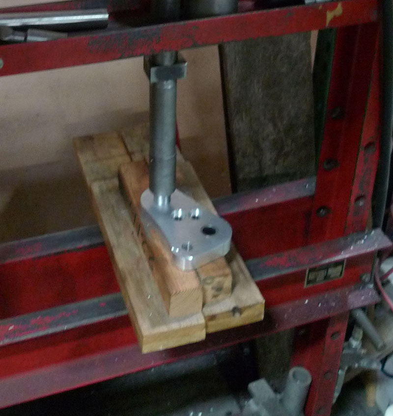
I used a hydraulic press to push the bearings into the leading link and caliper mounts
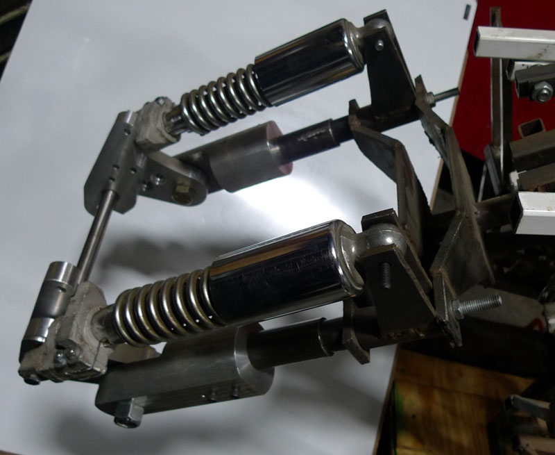
And here is the new front end! Very nice! Note the only cast pieces now are at the ends of the shocks.
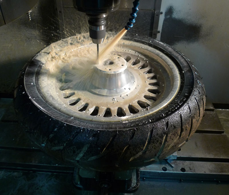
Next I glomed a tire / wheel from the shop, I wasn't happy with the tire / wheel combo I was using. Unfortunately this one only had holes for the brake rotor on one side, so we stuck it in the CNC and drilled and tapped 5 holes to make it a dual rotor.
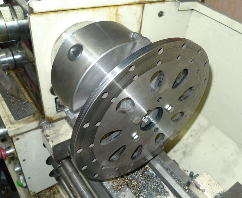
The rotors I had around the shop didn't have a large enough internal diamater hole so I put them on the lathe to open that hole up
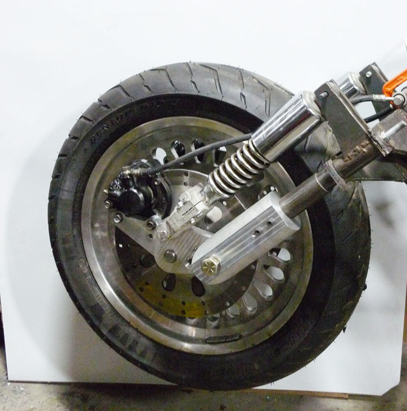
The Front End, current progress, looking good! It's still missing a piece though...
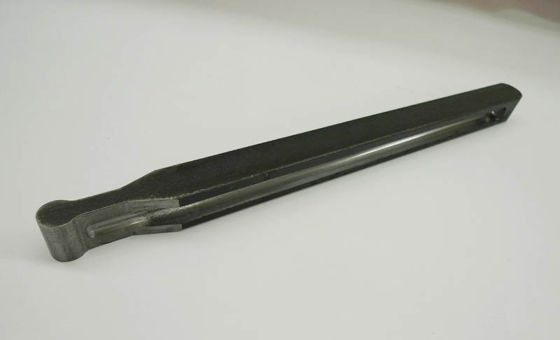
Next we machined a pair of torque bars out of 1" solid square steel bar stock.
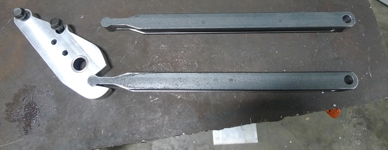
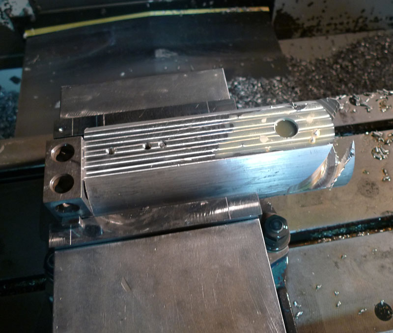
This image shows where they fit, and after the mounting hole was drilled into the back end. The aluminum piece on the left is the caliper mount, this holds the brake caliper, the part that actually squeezes the rotor and slows you down. Notch allows it to rotate about 20 degrees. You might be wondering why I didn't make this a clevis joint or just drilled a hole in it, the main reason is there simply wasn't room between the existing fork tubes and I would have had to remake my entire fork. But the force on these is a pushing force, not pulling force, so the notch should work well.
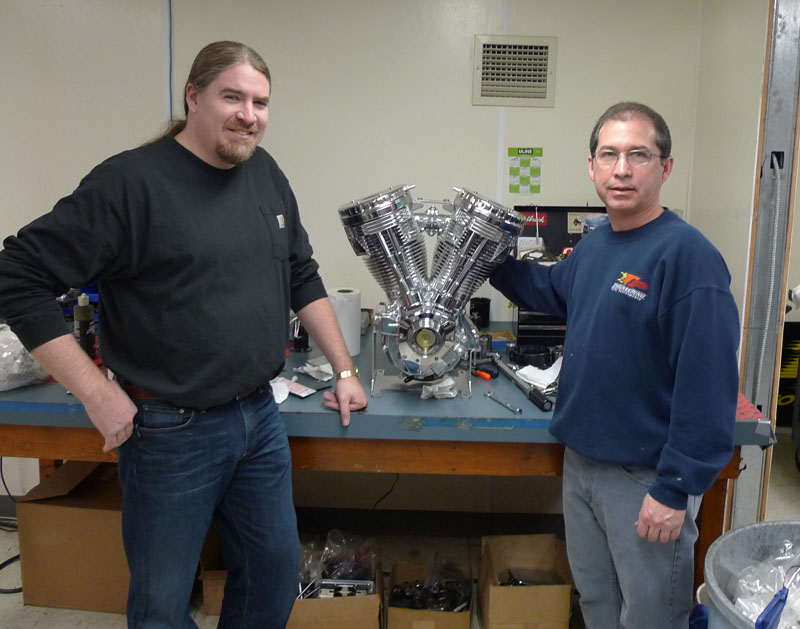
Around this time I took a trip out to CT to rebuild one of our motors that was from one of Paul Jr's builds. This is the motor that was submerged and damaged from hurricane Sandy.
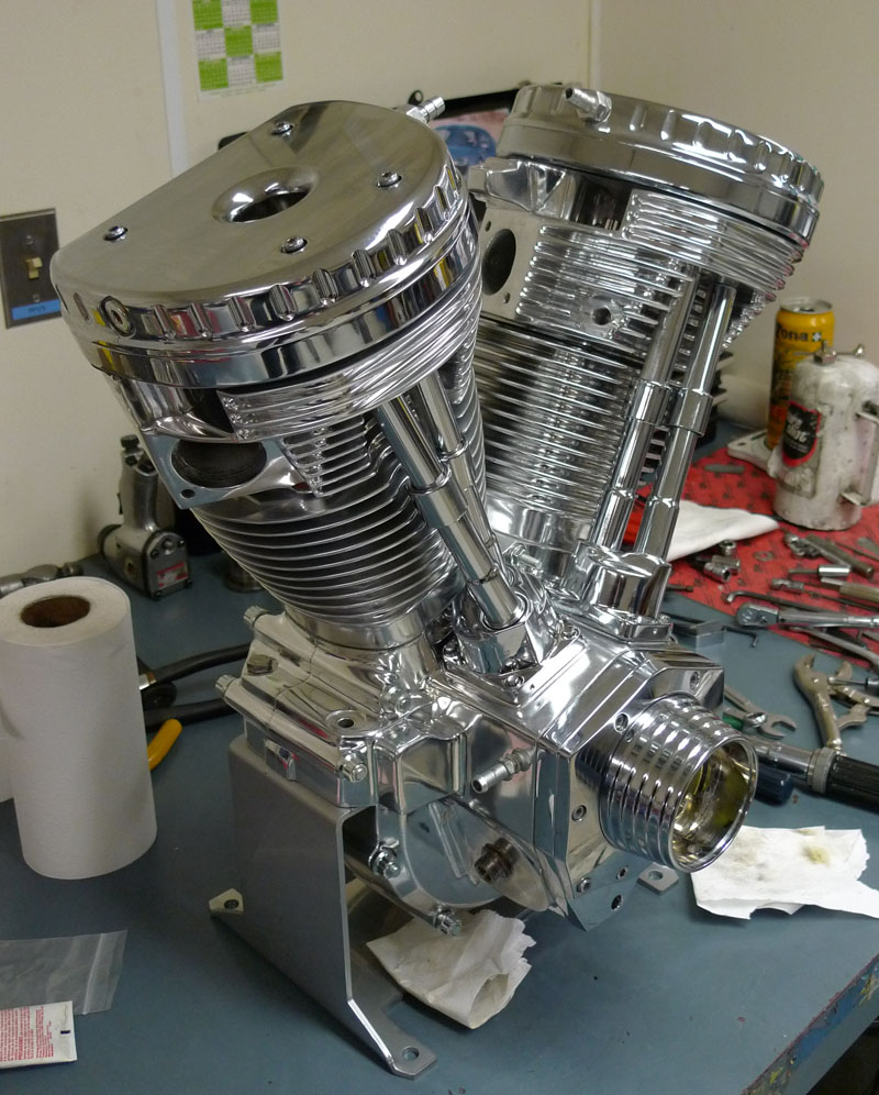
Here is the completely rebuilt motor, beautiful!
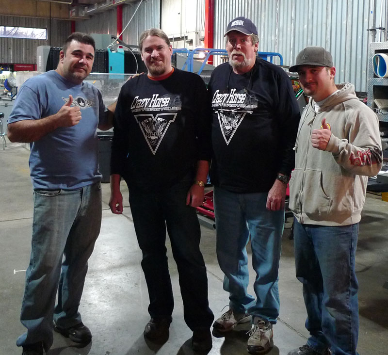
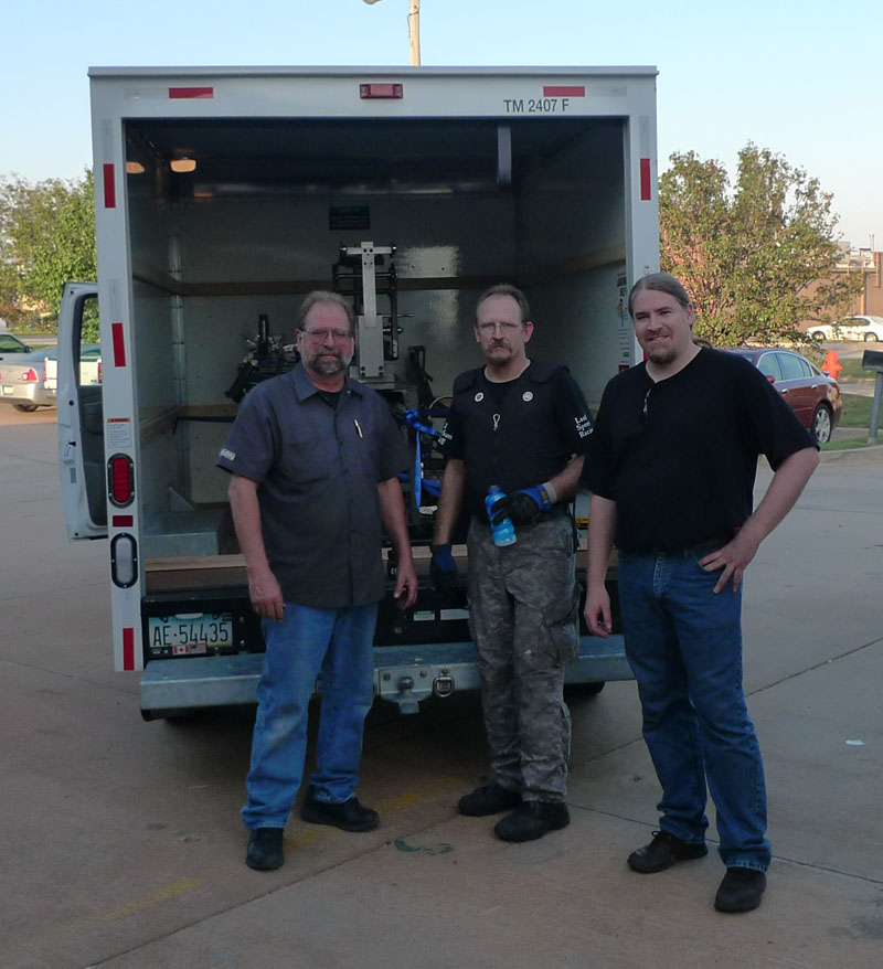
My father and I dropping it off at Jr's shop, meeting Vinnie and Cody
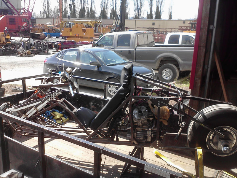
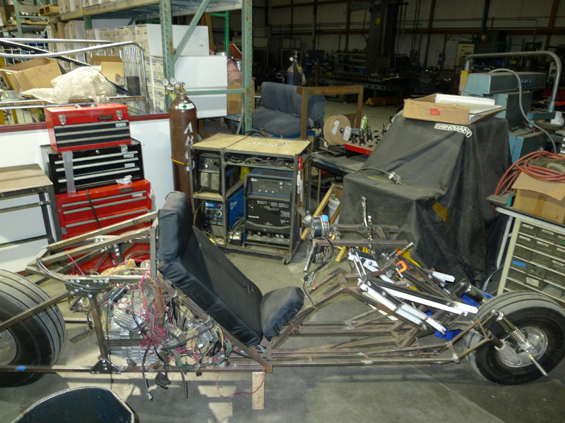
In the Summer of 2013, we had to move our entire shop out of the 10,000 sf facility we had been in for years into a 2,200 sf facility about 10 miles away. Here is my bike project loaded up and being moved... again... =/
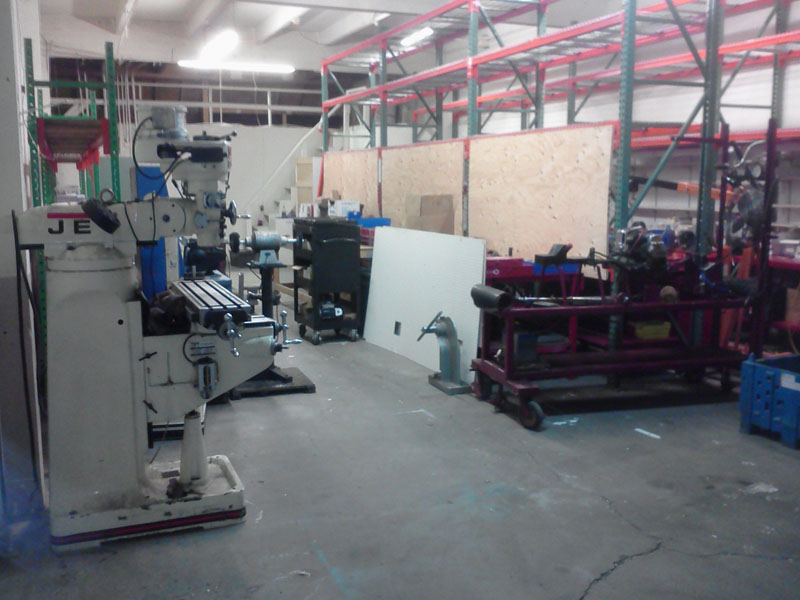
Setting up things in the new shop
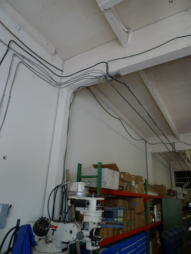
Getting everything wired up AGAIN. This is the 7th time I've had to do this.
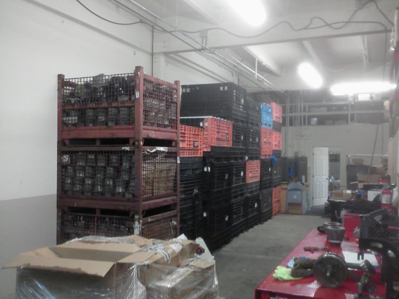
Making room for almost 30 full pallets of motorcycle engines cases, heads, and cylinders. Each palette weighed over 1,000 lbs. Because our pallette jack was the wrong size, there was alot of hand dragging these pallets across the floor of the truck that brought them. Man what a work out. Cross Fit take note
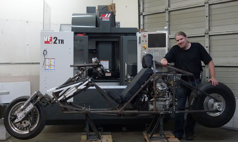
Soon we got a VF2 again, here I am with the bike and the CNC
|