Unfortunately my Kickstarter program was unsuccessfull, but I deeply appreciate all the pledges I recieved. However, the press I recieved from the Kickstarter launch attemp brought me to the attention of Crazy Horse Motorcycles, which flew me out to Seattle, WA (from Connecticut) to tour their shop and meet the team. They pledged to donate a 100+ HP Power Plus V-Twin engine to my build, and some discussions I am extremely pleased to announce that I will be:
- Moving to Seattle and Joining Crazy Horse Motorcycles
That's right, I will be joining the Crazy Horse Motorcycle team and will be designing and building bikes professionally, this is an incredible oppurtunity and the team I will be working with are a great bunch of ambitious and intelligent people, I will also be setting my bike up in the shop and will have access to their shop equipment to continue working on my project. Fantastic!
- Rolling Chassis Completed
As the move to Seattle approaches, I rushed to get my Rolling Chassis completed and to get my shop packed up, check out the first videos of the rolling chassis here
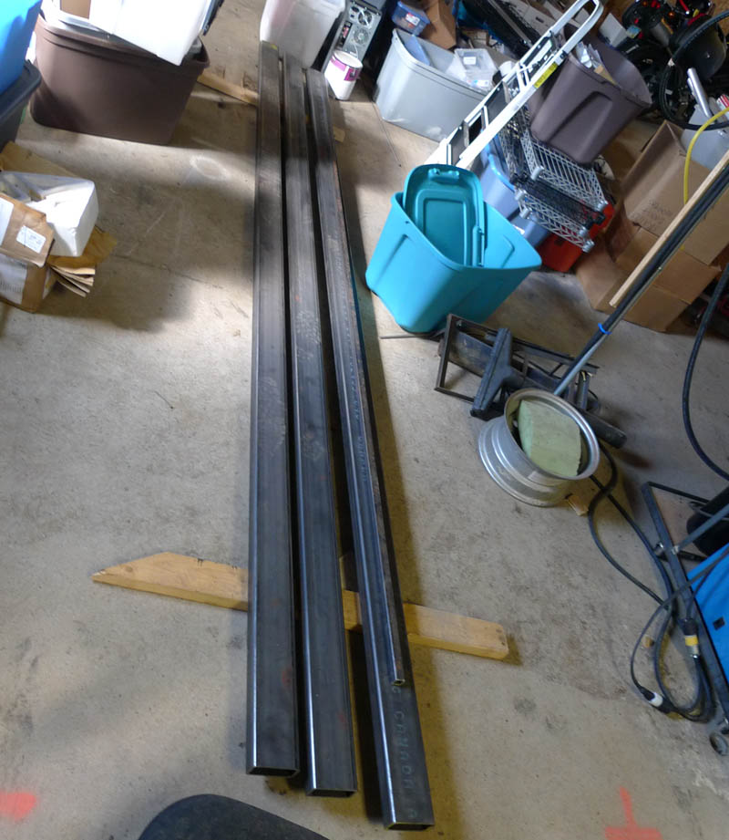
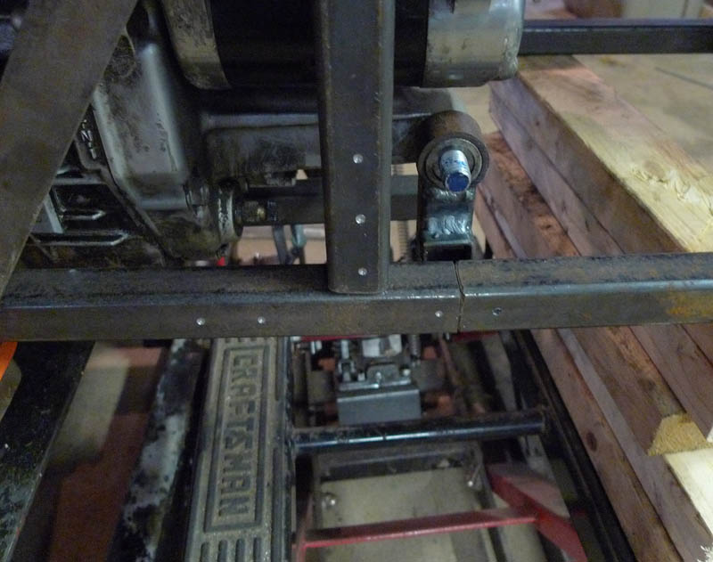
On to the detailed update - Last we left off was with the completion of the updated stiffer virtual pivot point assembly. With the move pending, I wanted to get my chassis rolling, to start with I had to build an alignment jig. Starting off with four 12' 2" x 4" steel beams, I begin chopping
It is necessary to use large stiff beams for frame jigs and alignment jigs as they must resist the twisting caused by the welding of the bike assembly
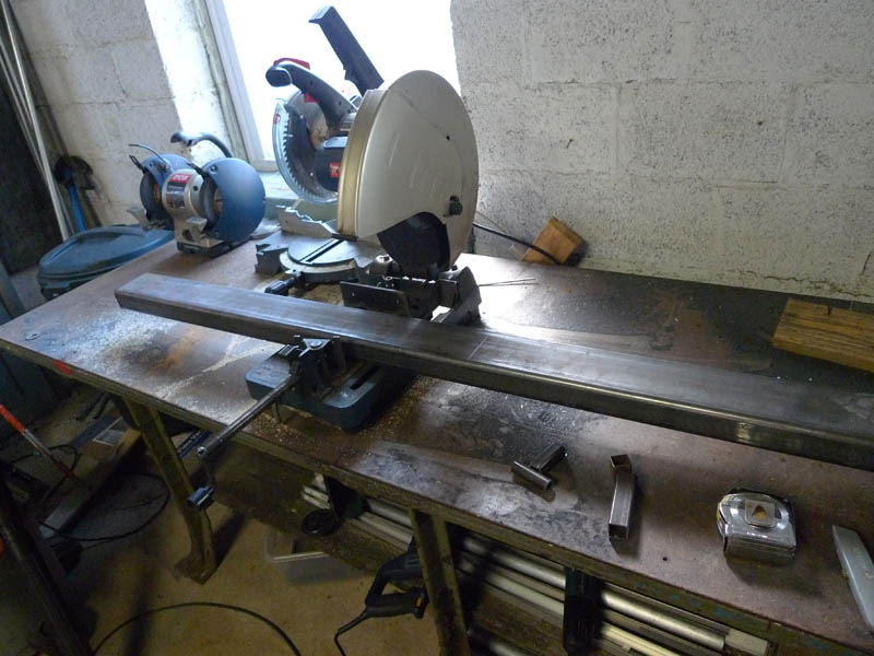
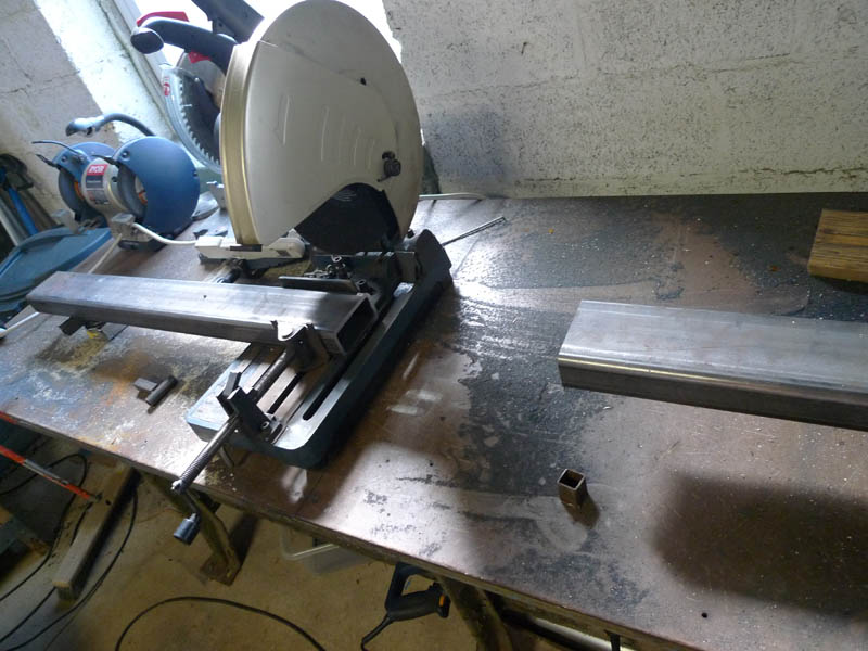
A few more cuts later:
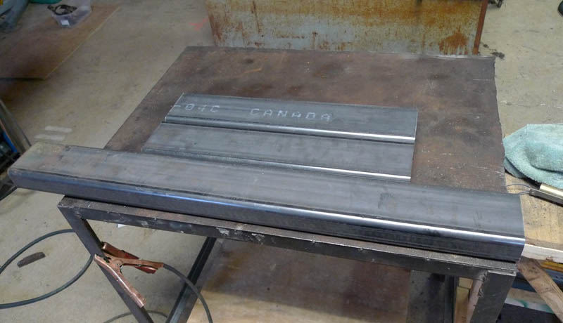
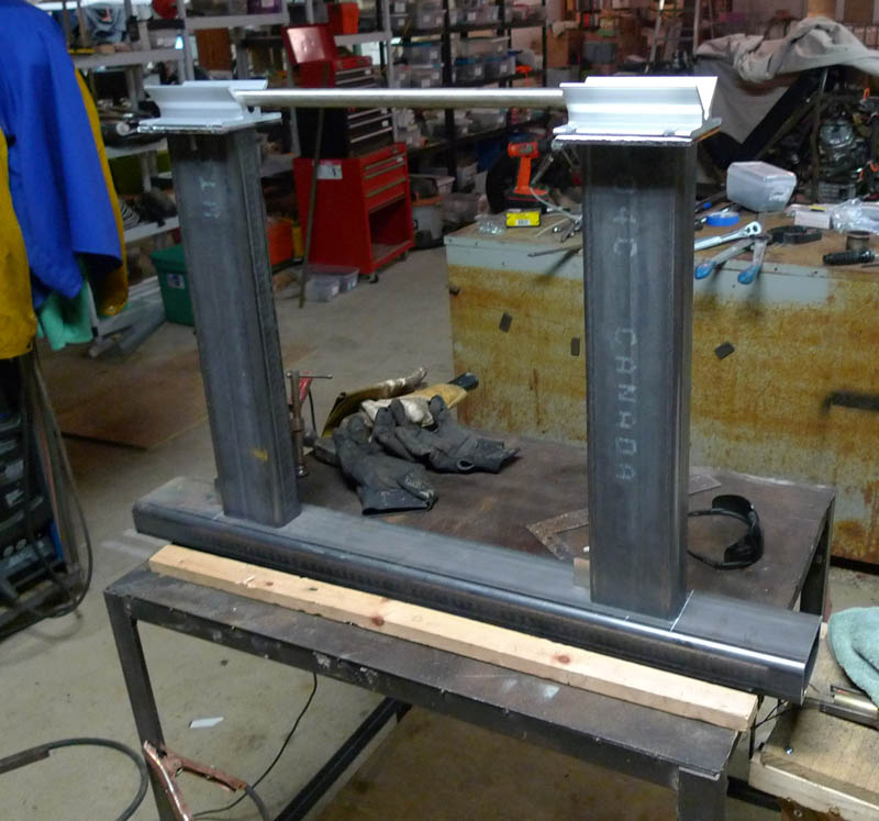
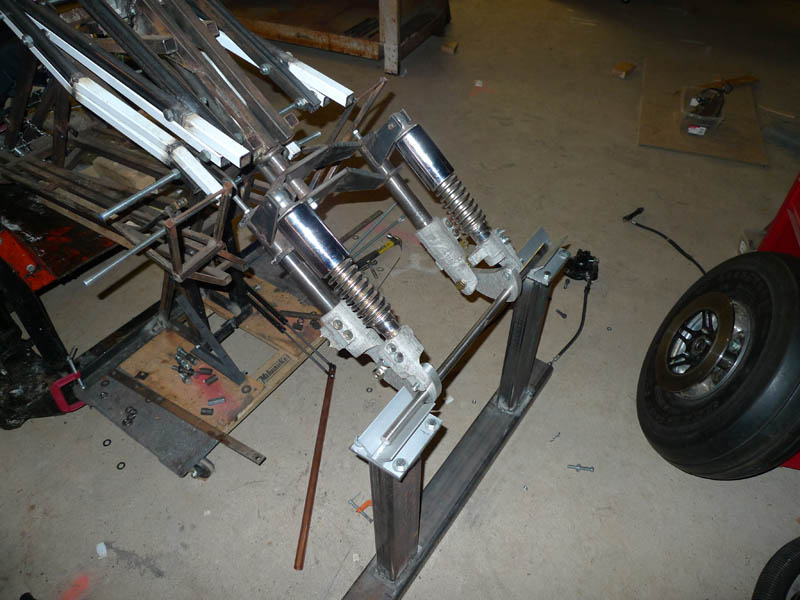
This is the base and the vertical legs for a front end alignment post, at the top of the legs two rectangles are cut with the plasma torch
These are welded to the top of the legs and V-Blocks are attatched.
This whole assembly will hold the front spindle straight with respect to the rear spindle
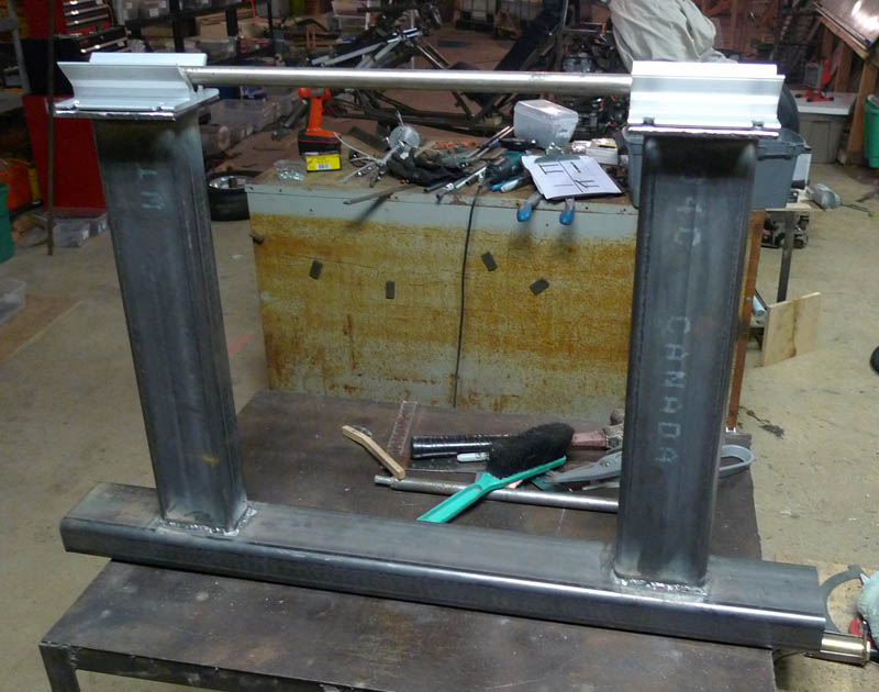
The plates are drilled:
And the final assembly is aligned and welded
The front end sits in this assembly like this
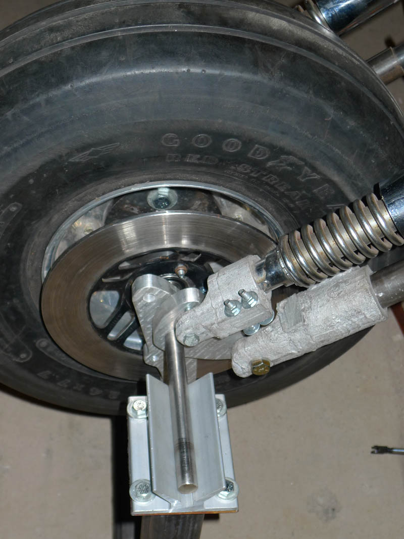
And here you can see the front end with brake calipers and rotors
This assembly made aligning the components of the front end much easier.
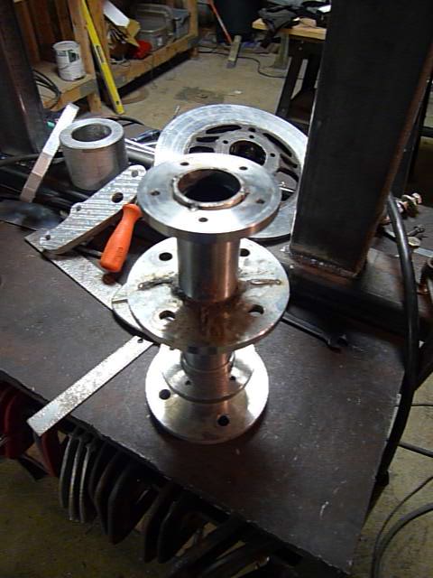
The rotor mounts required some especially careful alignment, which I won't bore you with
The end result of the central hub with brake rotor mounts is below
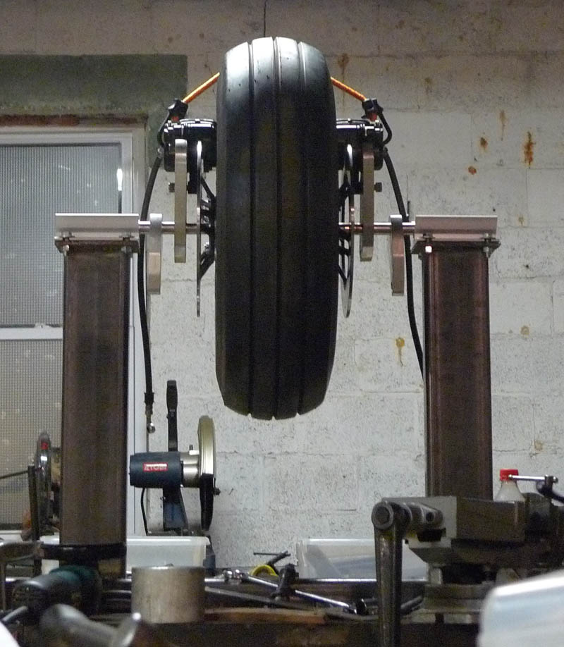
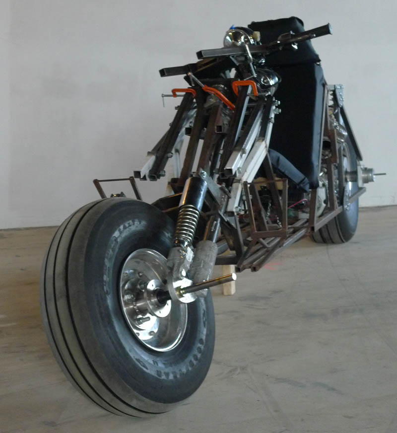
And here is the front end, straight on, where you can clearly see the leading links and brake calipers
Lifting the bike and putting the front end on we see this. Here you can see the spindle resting in the V-Blocks of the front alignment jig
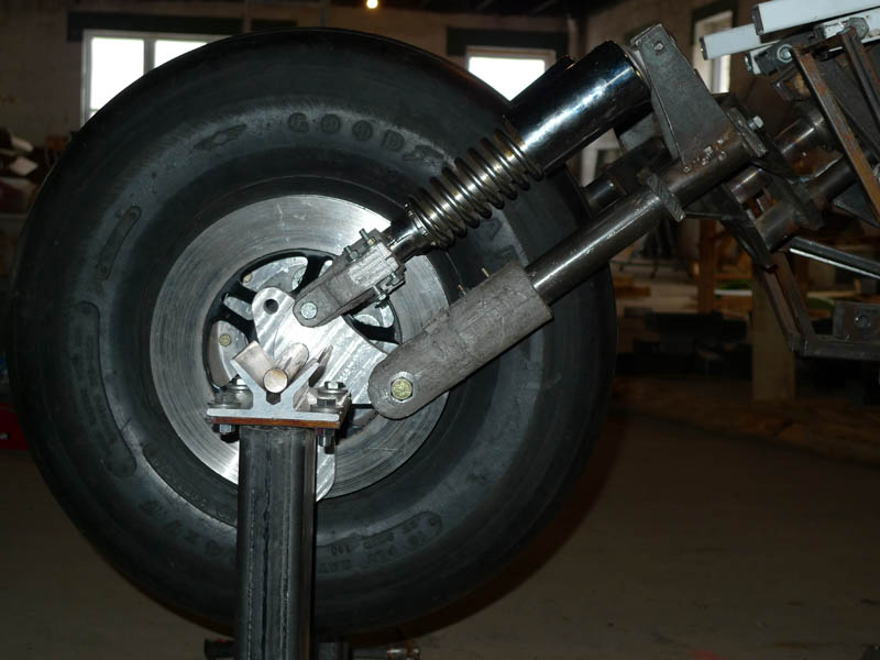
And now with the wheel on (actually there were many many steps between these two events that were all based on trouble shooting problems with the front end as well as trying to lift / hold the bike while putting the wheel on)
A closer view
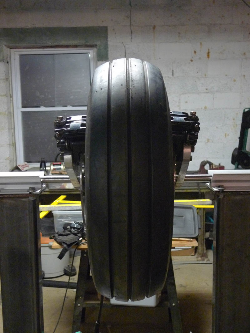
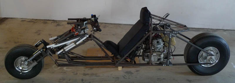
And a side view
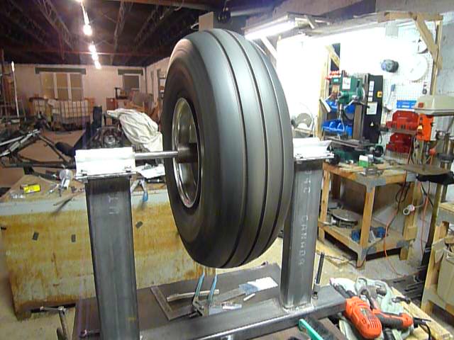
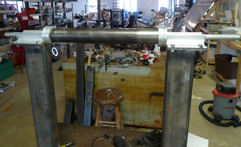
Next we are on the to rear wheel alignment jig, after much cutting, aligning, and welding we have the following:
In this case the spindle is a much larger diamter (2 1/4") for reasons you'll see later, the small cups on the end are aluminum pieces with a groove machined into the to recieve the edge of the spindle, then the whole thing has a 3/4" rod going through it to mark the center.
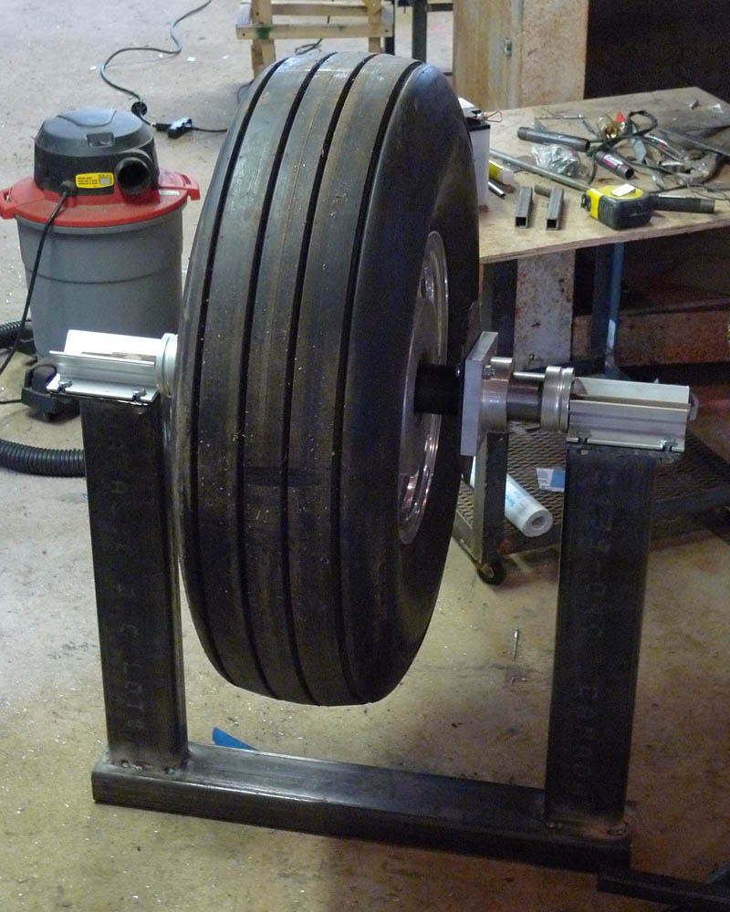
Here is the rear wheel on the spindle on the alignment jig
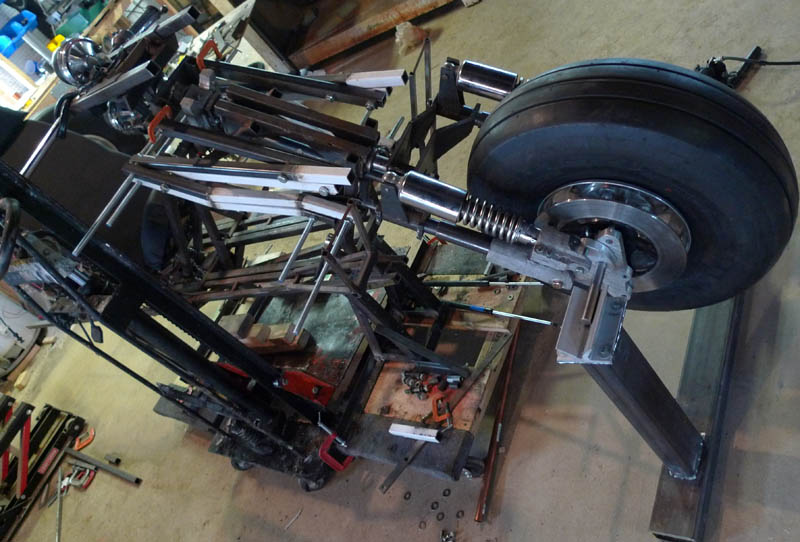
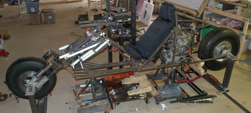
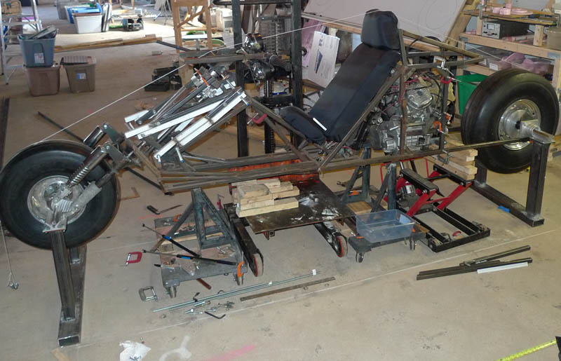
And now the front and rear are both in place!! Still need to align the front with respect to the rear and tack weld the whole assembly
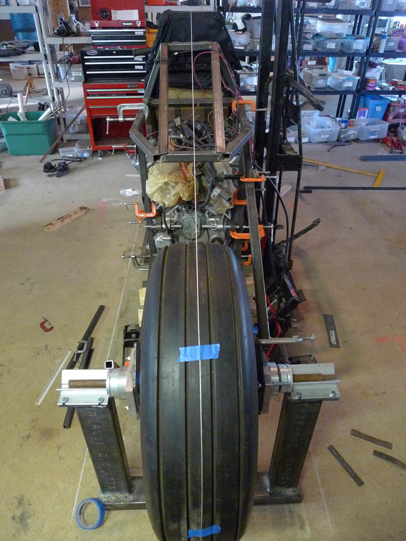
For starters a string is placed at the center of the front and rear wheel and along the centerline of the bike, it makes noticing misalignments much easier.
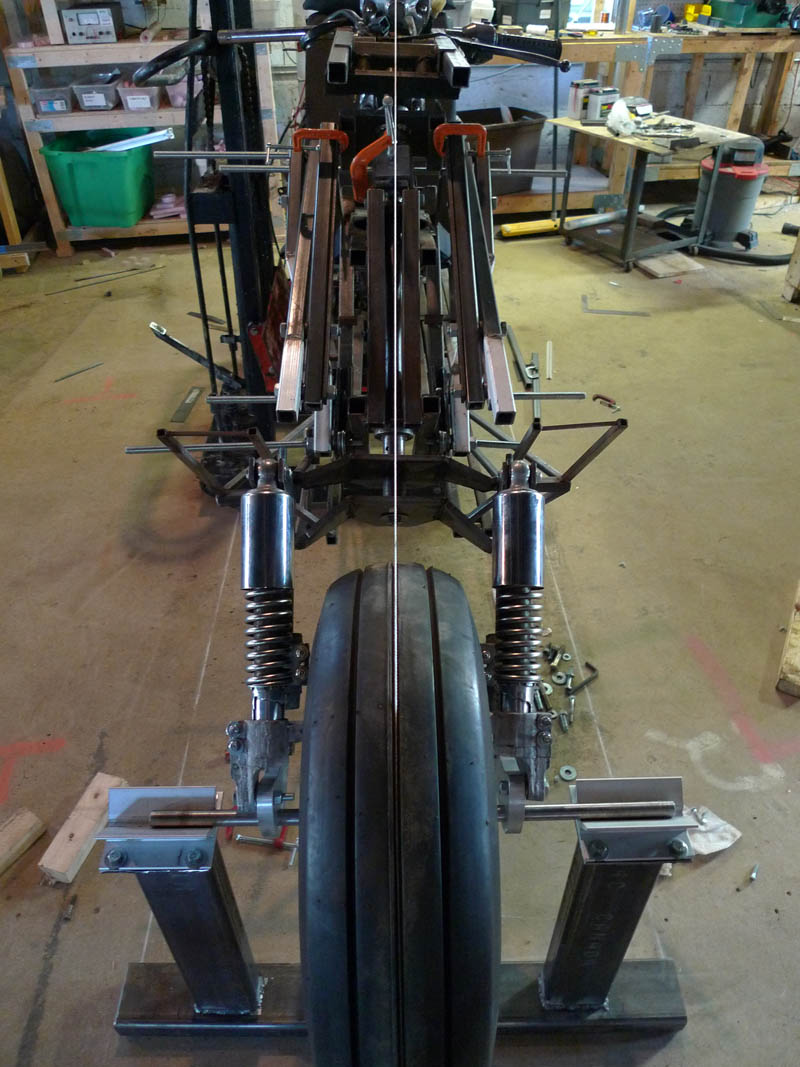
View from the rear wheel, after alot of tweaking and tapping we see we have a pretty good alignment.
And from the front, pretty good as well.
Notice those chalk lines on the floor, I used those to measure the distance from each leg of the alignment jigs and made sure with a large carpenters square they are at 90 degrees.
The next part then is to permanently attatch the rear spindle and wheel to the bike. Well not permanently, as I noted before, the whole rear assembly will be easily removable to facilitate trouble shooting / upgrading / modification etc.
This you tube video shows the goal:
Some modifications were made to that idea, but the basics remain.
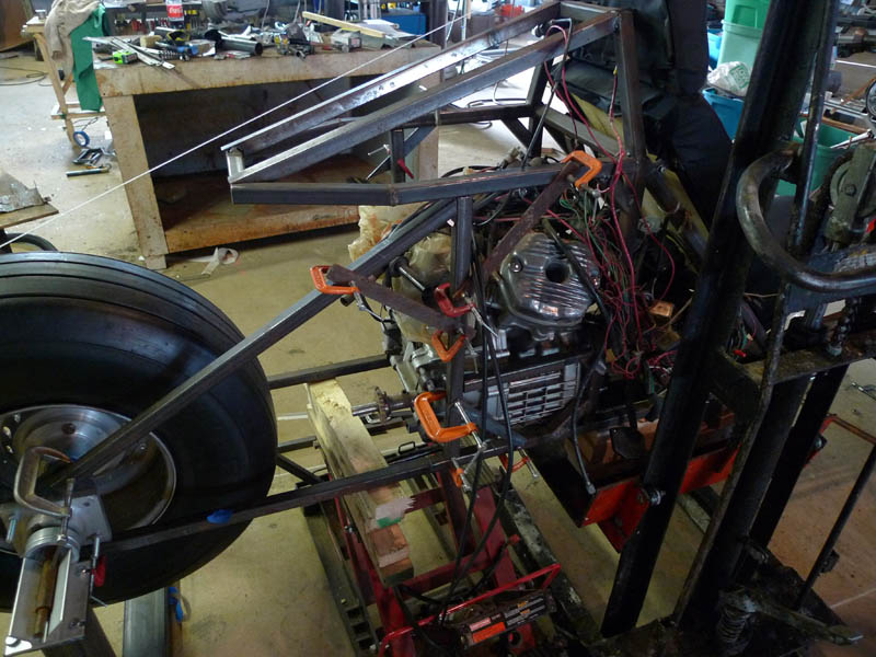
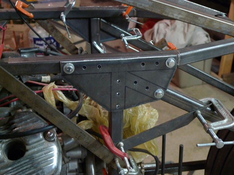
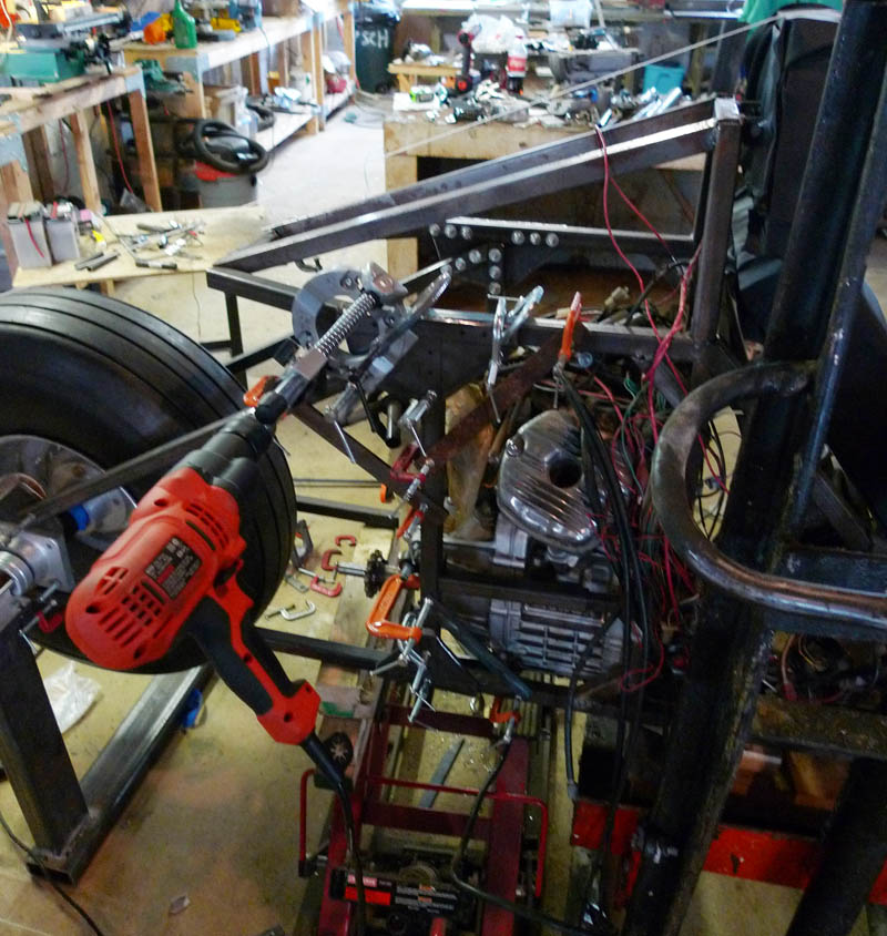
To force the frame parts into alignment small 1/4" x 1" bars are C-Clamped over adjacent tubes to hold them in place
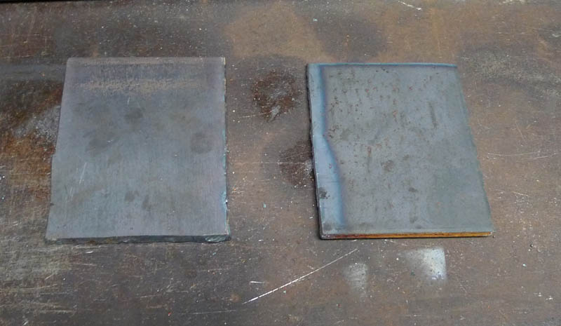
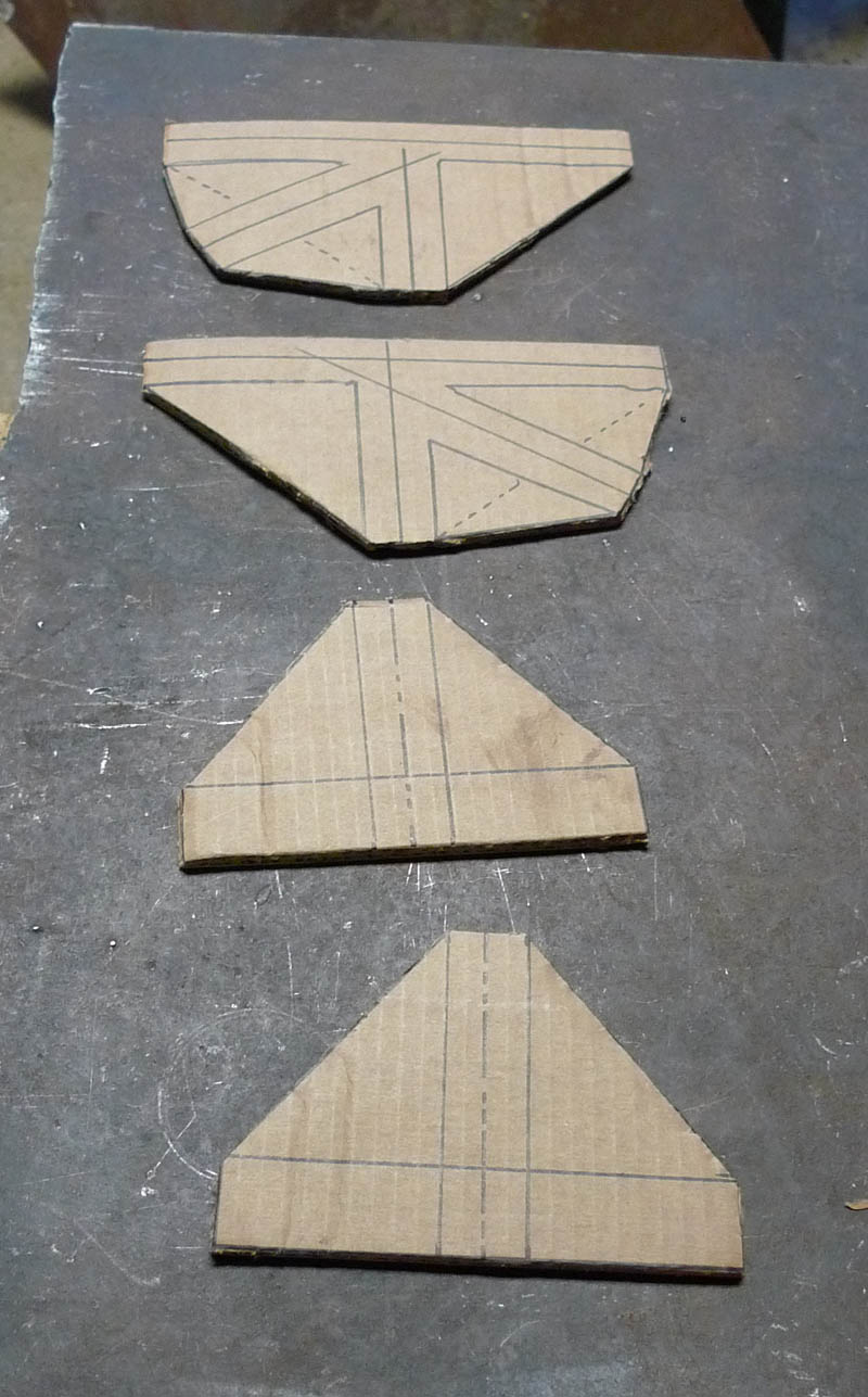
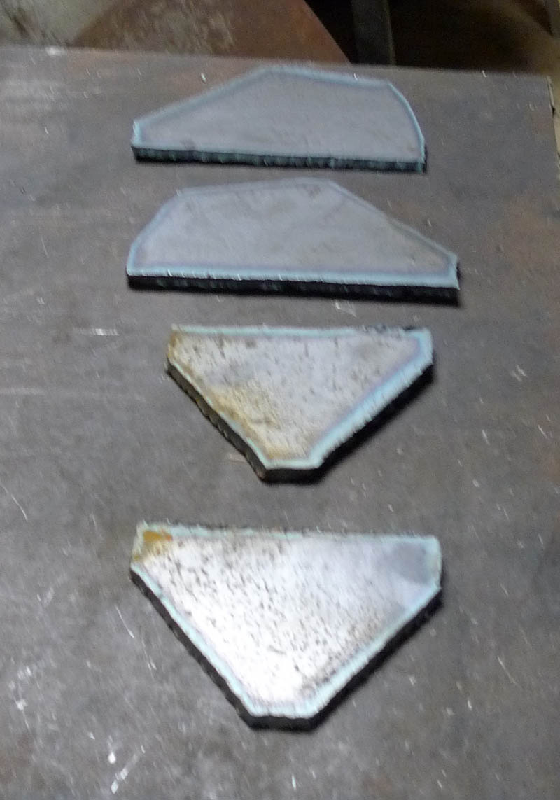
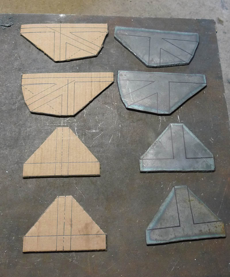
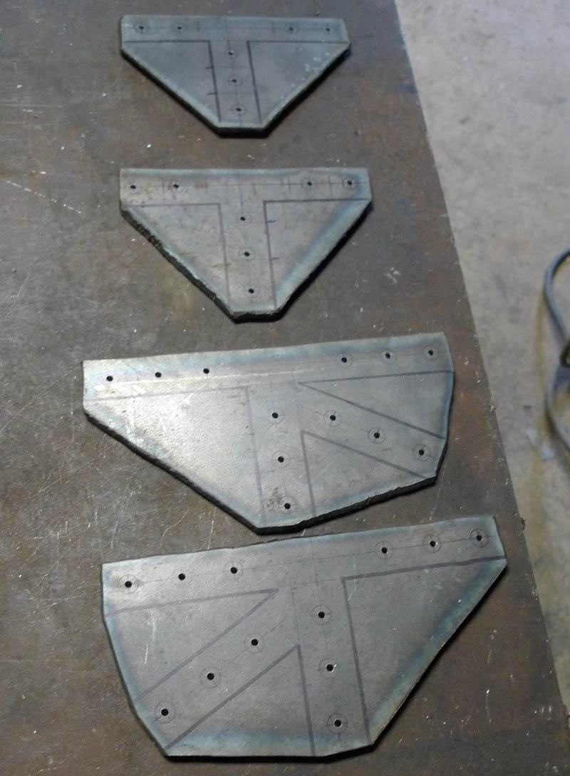
The plates to be cut are then traced out of cardboard
And then cut with the plasma torch out of 1/4" steel plate
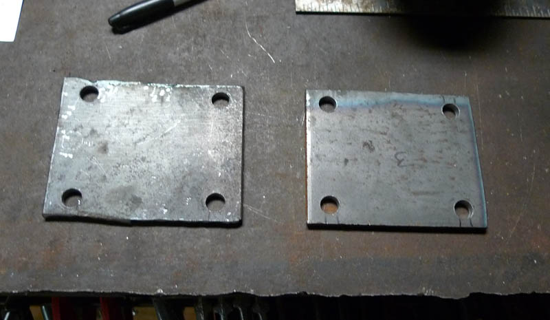
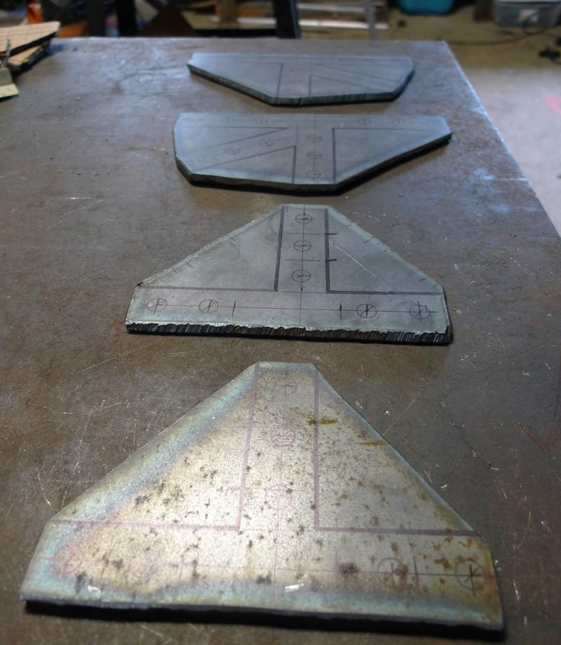
Marked and getting ready for drilling
Accurately marked and center punched
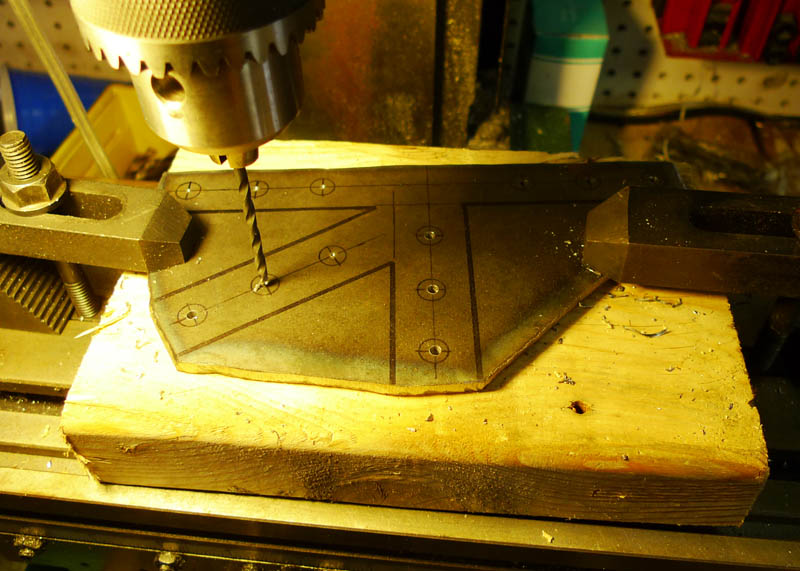
Drilling commences
All pilot holes now drilled
The frame tubes are marked and getting ready for drilling
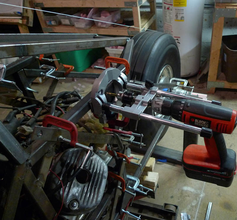
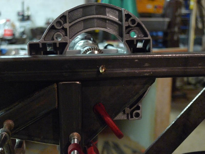
It was absolutely necessary to clamp a drill guide to the plates and use the plate and drill guide to force the drilling through the frame to stay in alignment. This was a very tedious operation and the holes took quite alot of effort.
A good drill right through to the other side
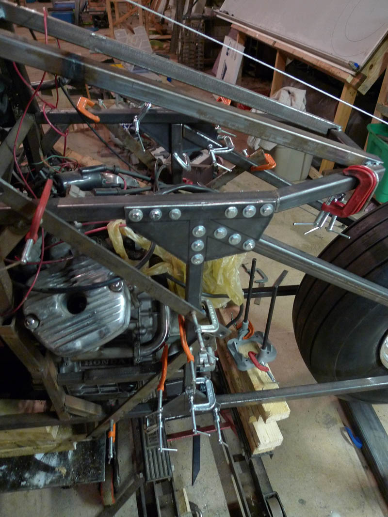
The first couple holes are now drilled and 1/4" grade 5 bolts placed through them.
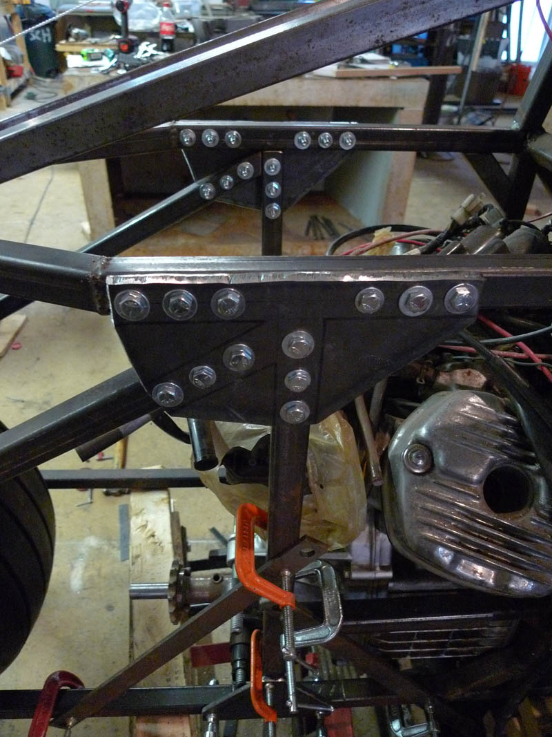
All the holes of the first plate completed!
I should note these plates are not an optimal design, really you shouldnt have sudden changes in thickness like these plates produce, those sudden changes produce stress concentrations and become the points of fatigue failure. But in this prototype I won't see enough mileage to worry about fatigue failure and I am not overly concerned with weight.
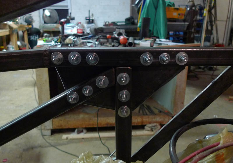
A nice view from the other side. These holes took alot of work to drill so I must show off a few extra pictures!
The left side now completely drilled and bolted.
Now onto the right!!
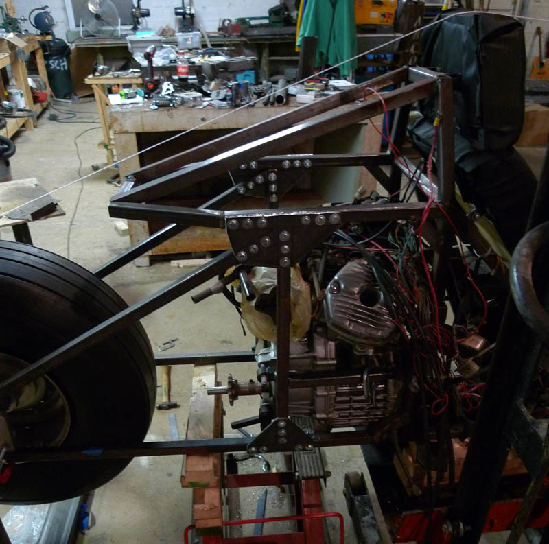
Right top completed
And right bottom completed... All done!!!!!!!
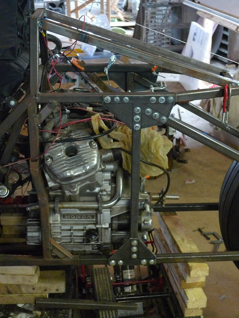
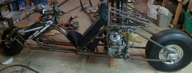
With those plates bolted and the ends of the tubes welded to the rear spindle mounts, this is the first time the front and rear axles actually supported the weight of the vehicle!
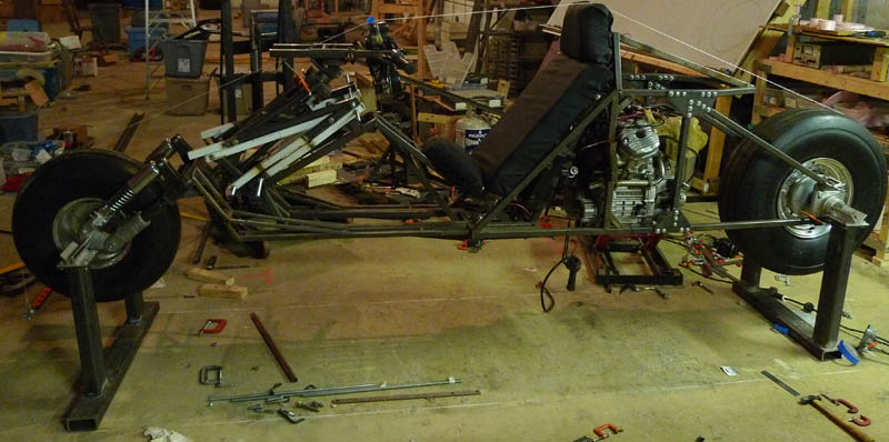
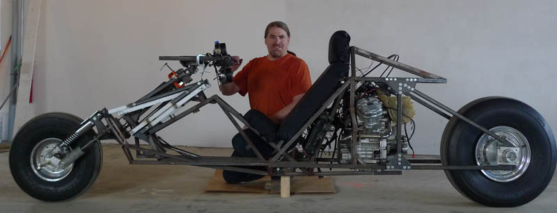
And lowered to the ground... Such a proud moment! My baby's first steps.
And so again, I must share the video of the Rolling Chassis (complete with Akira movie music)
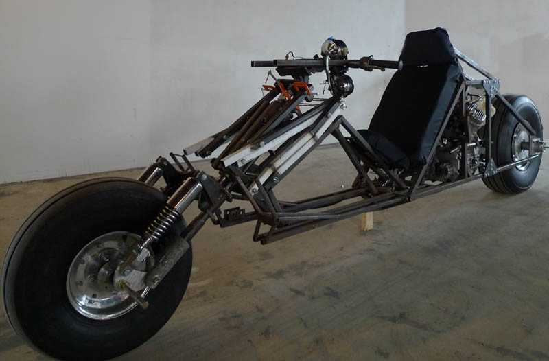
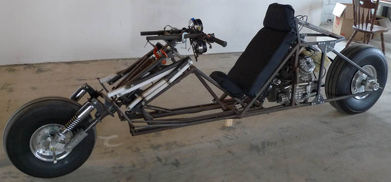
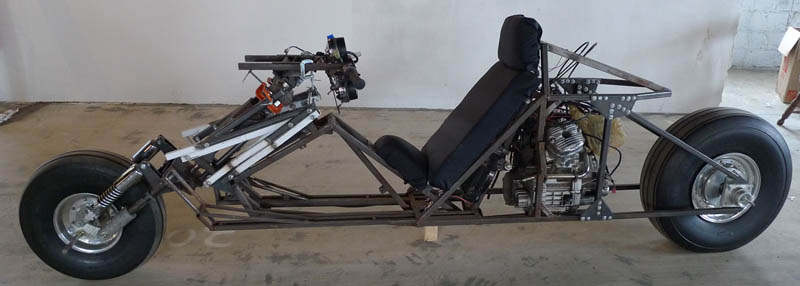
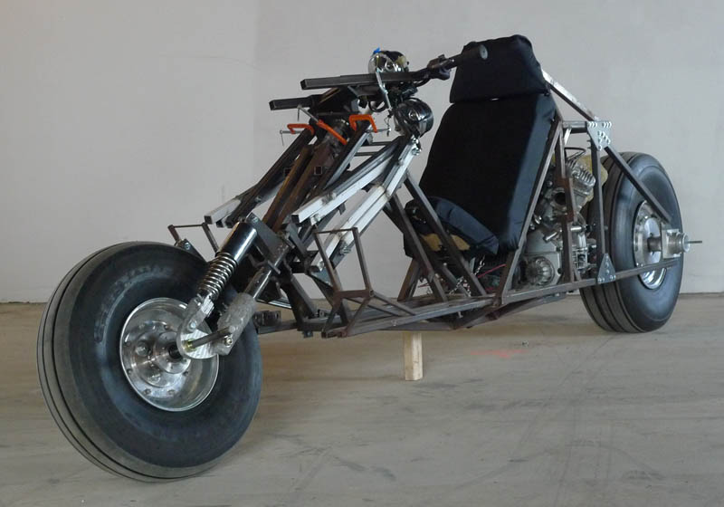
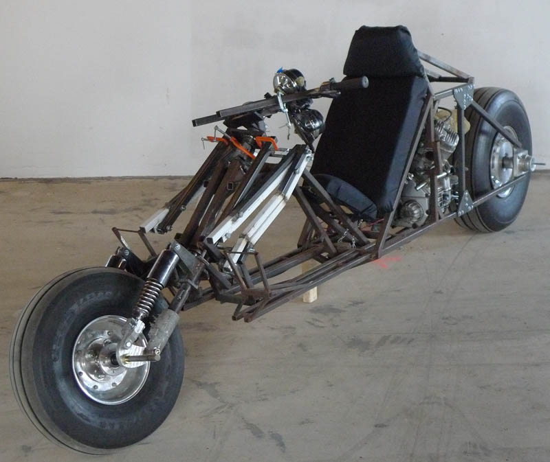
A few nice pics of the Rolling Chassis
And of course me with my contraption
That's all for now, I won't bore you with details of the move, but next update will be from Seattle!
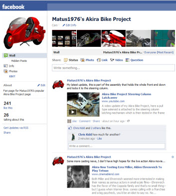
Please LIKE the Matus1976's Akira Bike Project in Facebook
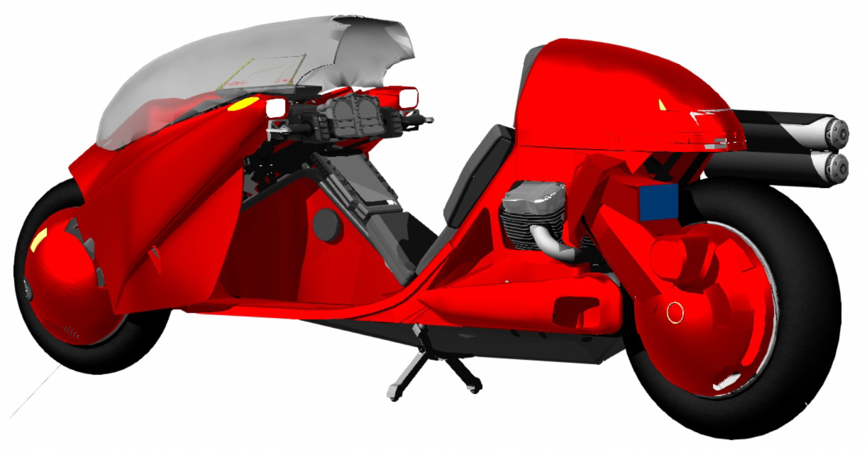
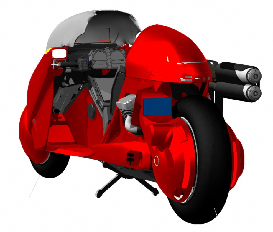
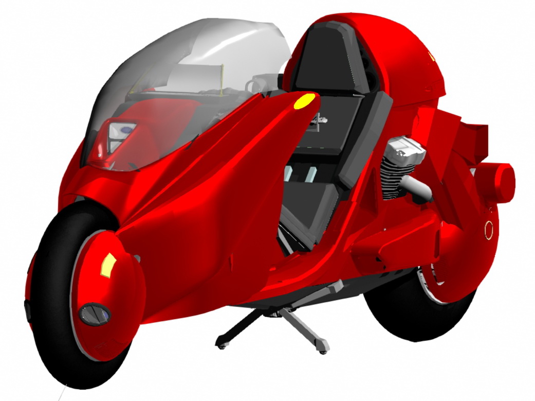
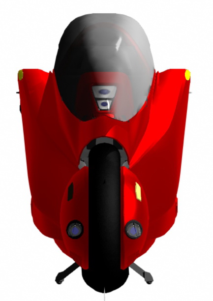
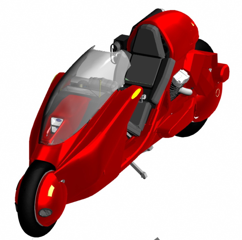
Production Prototype
This is a highly detailed and accurate 3D model of the current production design, some changes will come about as a result of further testing of the prototypes but this represents very closely what the finished product will look like.