Thank you for loyally sticking with the project, through lay offs and a bad motorcycle accident I've perservered.
Some big news in this update.
1) I have a new stiffer stronger Virtual Pivot point system which facilitates the Powered Egress (Just like in the movie, the whole front end rises up) (see pics and txt below)
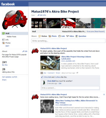
2) The Forum will be disabled, I am just overrun with spam, please visit the Facebook page and post all the comments and questions you'd like.
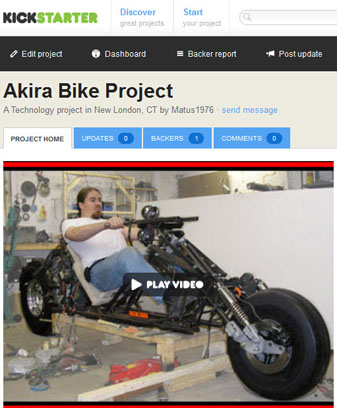
3) I've launched an Akira Bike Project Kickstarter account!!!
Check it out, along with my intro Video...
If you ever want to see a fully functional Akira inspired bike hit the road, please consider contributing, you can contribute as little as $5 USD all the way up to $10,000 USD.
None of your money leaves your hands unless my project hits its goal, so you can be assured your money is going to be used well. Kickstarter is probably the best known of the "Crowdsourcing" sites and has been featured in major media sources such as CNN, Wired, and the New York Times
This is a huge deal everyone!
If you ever want to see a recumbent motorcycle on the market, please support the project.
If you ever want to see the motorcycle market evolve beyond the safety bicycle of the 1890's design, please support it!
If you ever want to see a safer motorcycle on the market, support it!
If you just want to see this finally finished, in the name of creative endeavors, please support it!
My project goal is $40,000, this will enable the completion and all testing and refinement of the functional prototype. With that on the road, I can raise the money to build the production prototype, and you WILL see an Akira Inspired two wheel steering rear engined high performance recumbent motorcycle on the road.
Please post the Kickstarter page to you Facebook, your favorite forums, twitter, etc. Every dollar helps.
Thank you everyone! no on to the Update...
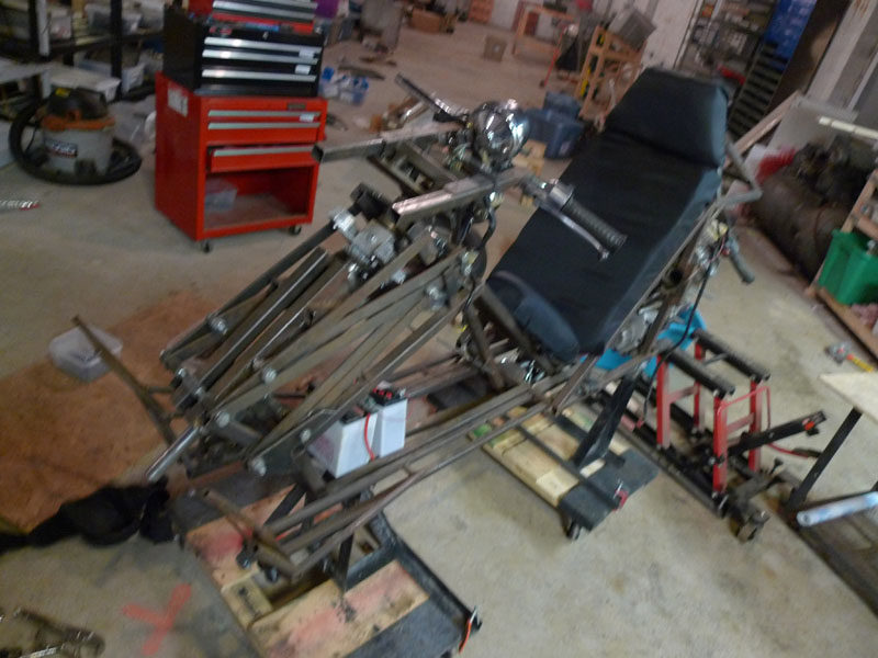
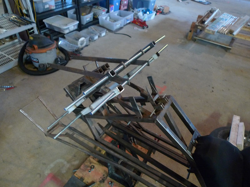
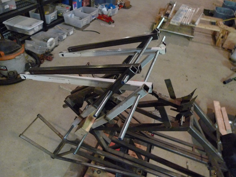
The current incarnation of the Virtual Pivot Point based Powered Egress had some issues, I decided to beef it up, upgrading from 1"x.25" steel bars to 1" square tubes.
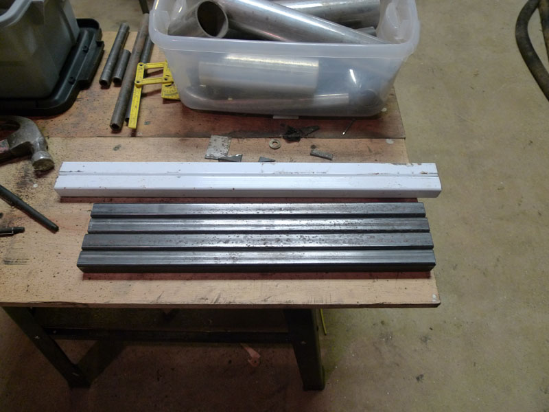
Here you can see the original design, the 5 bars on either side are 1" x 1/4". They lacked the stiffness necessary and were too narrow for the new internal locking mechanism
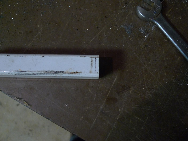
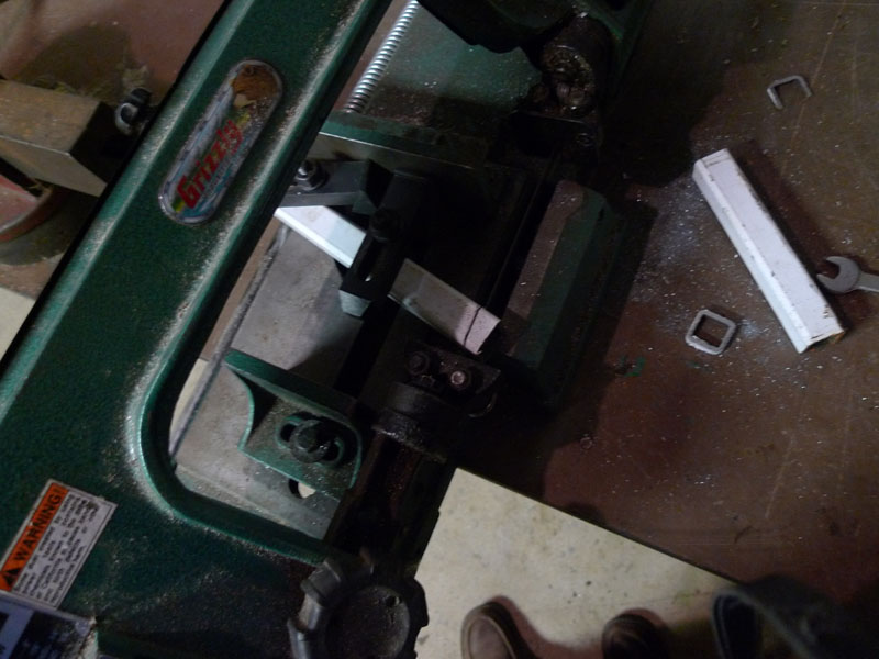
First I had to get my small bandsaw to cut a good square edge, above is the result after an hour of alingment and a dozen test cuts...pretty decent.
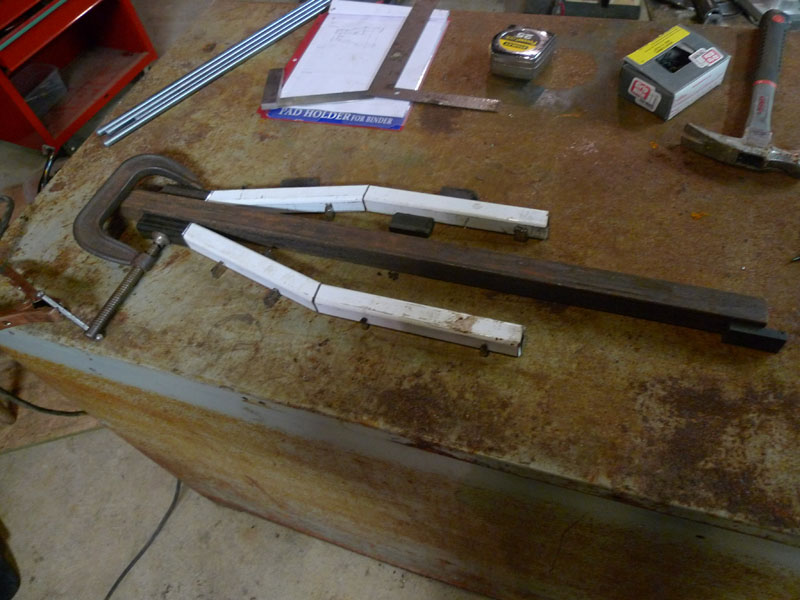
The bottom pairs of bars have an angled section to increase the width, here are the ready cuts. I found the clamps from my milling machine much easier to work with here than the built in clamp
Good Cut!
Next Piece
Here is one of them cut and both pairs of bars lined up
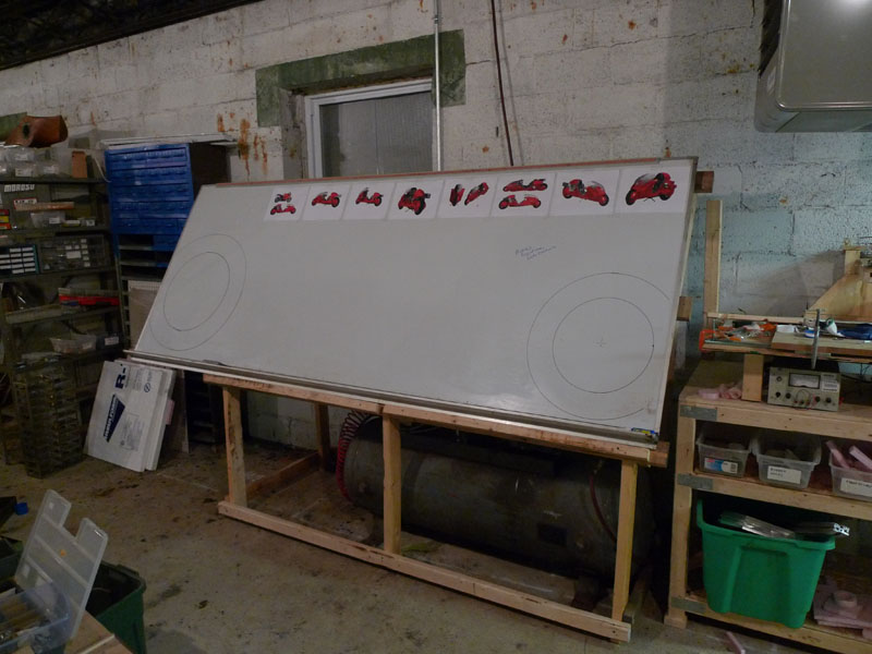
Interlude - moving my giant white board on top of my air compressor to save room
Perfect fit! ok back to the project...
Both sides are cut here and lined up for spot welding against a central bar. A much beefier jig should be used here but instead of making one I was quite meticulous with my spot welds.
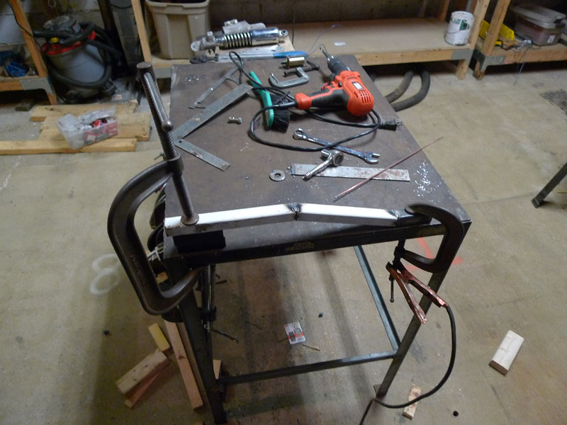
Clamping them to my steel / concrete workbench for final welds
Both pieces now complete
The next pair is almost the same
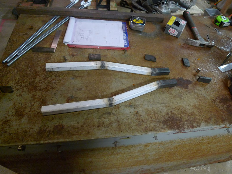
Both pairs now complete and laid out for comparison
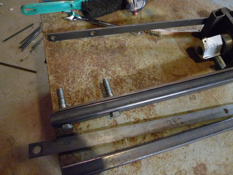
The next six bars are straight shots, but everything has to be cut and measured and especially drilled with a high degree of accuracy for all the rotational points to work out well.
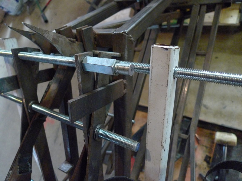
The old bars have all been stripped off and I've inserted two threaded rods to ensure alingment with the mounting bracket.
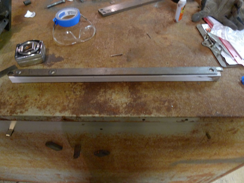
Now the hard parts, centering and lining up the holes. The first once just needs to be centered along the length of the tube.
Scoring and using a center punch, then starting with a very small drill bit is the best way to go. I didn't score it, but it came out very well here.
Now it's mounted onto the bike. I replaced some of the other bars for reference to make sure everything continues to line up.
The other side is done and drilled now as well. Everything still works well.
Now the next two bars are drilled, but only at the bottom, the upper two holes have to be lined up precisely with the existing pair.
Now I could have measured them in reference to the design only to find they didn't line up, or I could try to line them up with the existing bars and fail, causing it not to work. I debated this and decided to go with matching it to the existing assembly
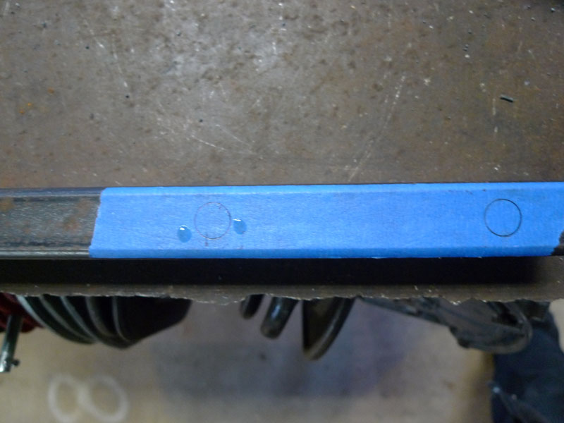
To help with the lining up process, I screwed a long nut onto the threaded rod and in the other end a bolt, whose head I cut off. I could press this up against the bar and trace it for a good accurate alignment.
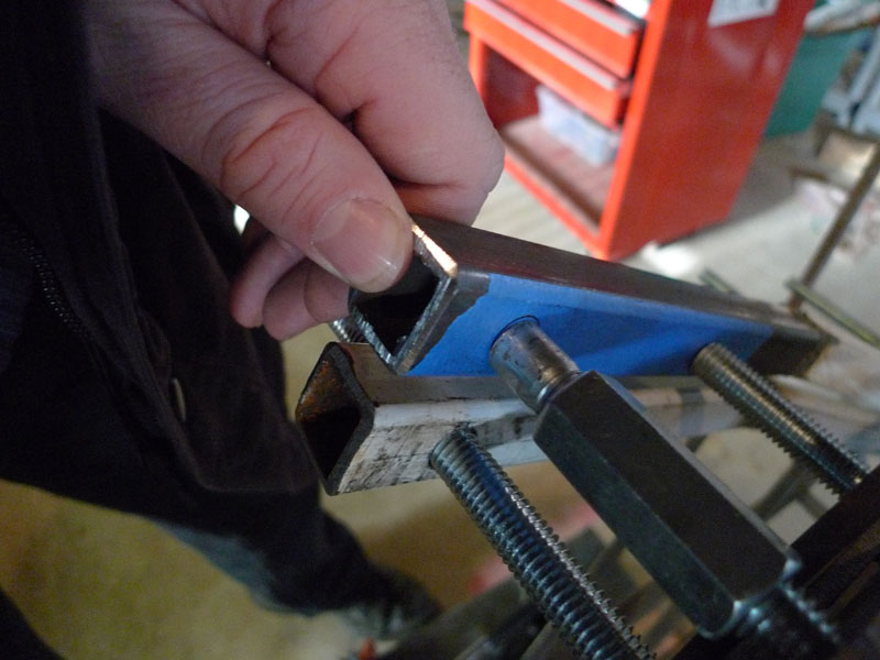
Very nice....Blue painters tape helped
Again, decent...
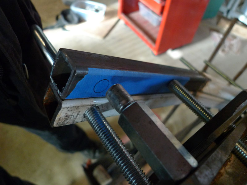
The two holes marked. The dabs of liquid are glue, I used a fender washer from my bearings to line up the holes so they are in the center of the tubes.
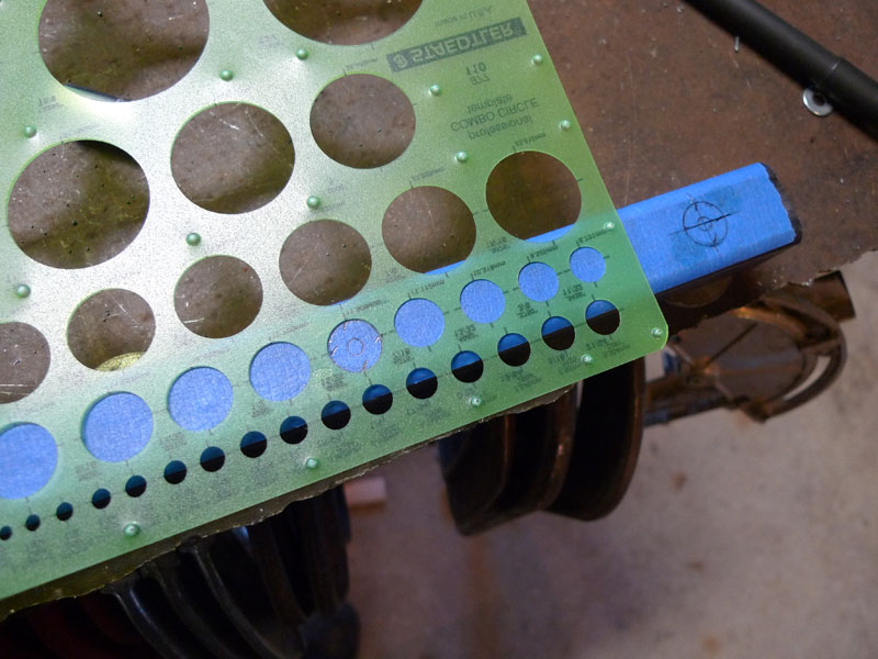
The drafters template helped find the center of the traced circle
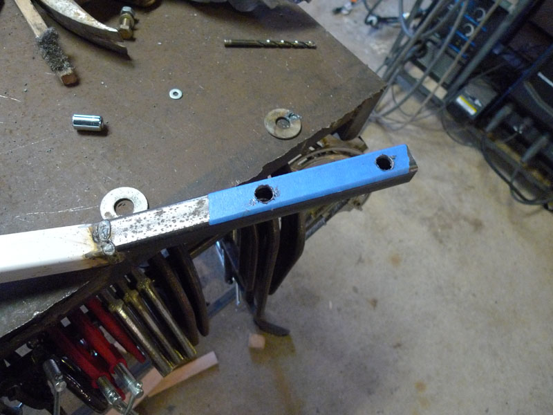
After marking with a center punch I drilled the holes and it came out very well
Now one of those bars are mounted and everything worked out well (mounting was difficult as threaded rods are not the greatest things to slide things up and down along... a rubber mallet and alot of patience were required)
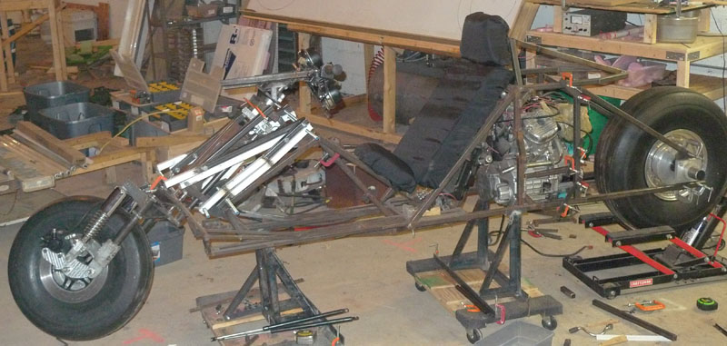
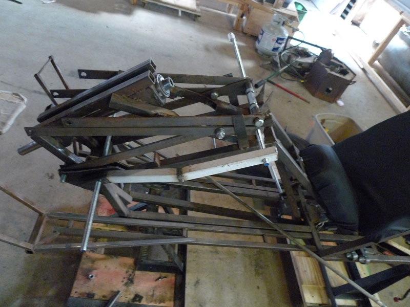
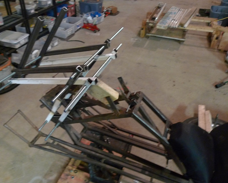
The other side is done, here the assembly is slightly raised up. Note the narrow bars are still present. They will be removed.
Another view, same thing. Looking good!
Now for the next bars. I chose to use the existing bars as guide templates.
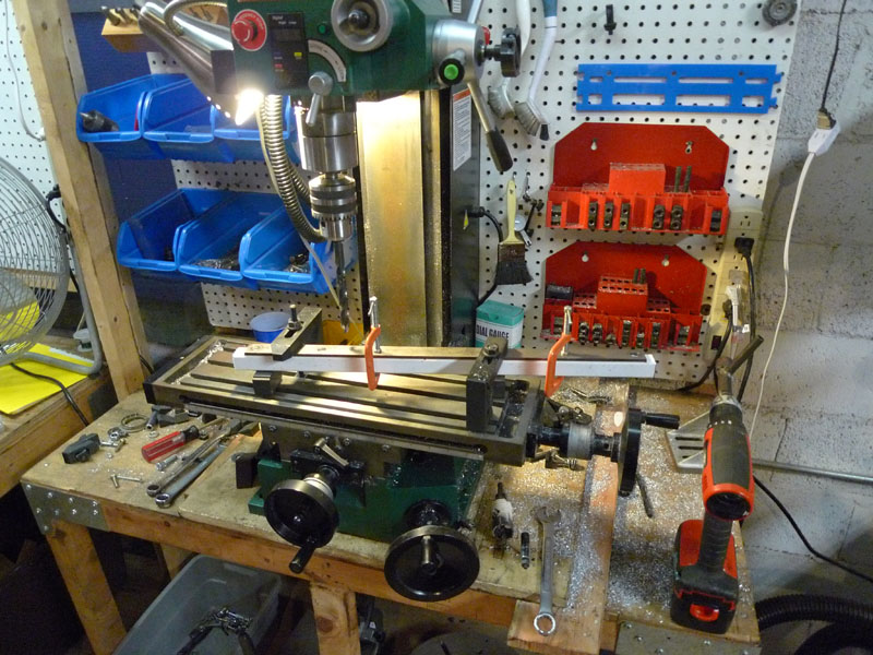
Bolting the existing bars to the new square tubes and mounting on the milling machine to ensure straight square drilling.
The next four bars are drilled and mounted. Still working great!
The last two bars were combined with the existing ones, it so happened the distance worked out perfectly. Obviously this is much heavier than necessary, but it's just a prototype...
Violla! Very Nice Very Nice...
Side View (with block of wood holding it up)
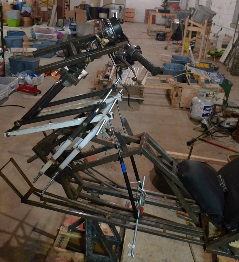
Now the actual handlebars are added
Side view with handlebars
Close up.
The bars will not stay like this, I'll be enlarging the holes and welding small tubes across and inside them, and the threaded rods will be replaced with solid rods and bolts.
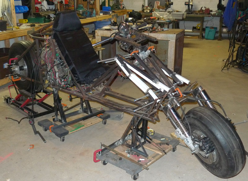
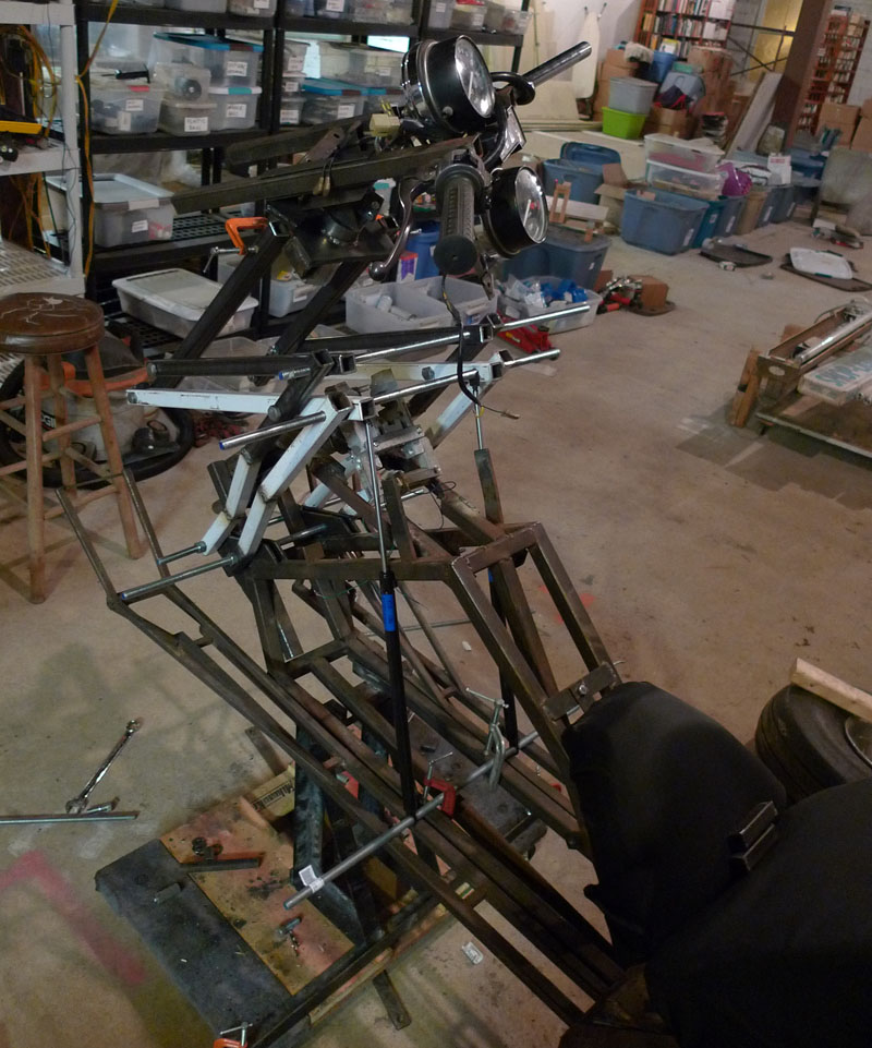
Fully raised up (again with block of wood helping)
Side view. A nice height here good for pulling yourself up and out with.
Now with Gas Shocks, these worked quite well at raising it, but were too strong actually to pull back down.
Looks good though. The problem was the stiffness in the upper most pair of bars that attatch to the handlebars. When you pull down, the play in the bars and holes and threaded rods conspire to not close the assembly as a set of parrallel bars, instead they bump into each other and stop closing. After I weld the center tubes I expect this issue to go away.
Other side, VPP raised with Gas Shocks holding it up.
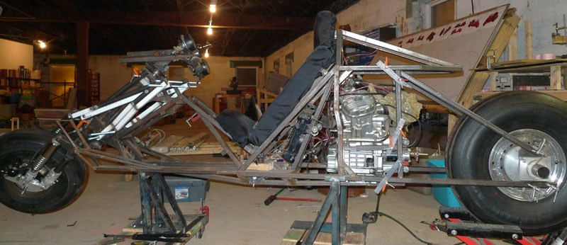
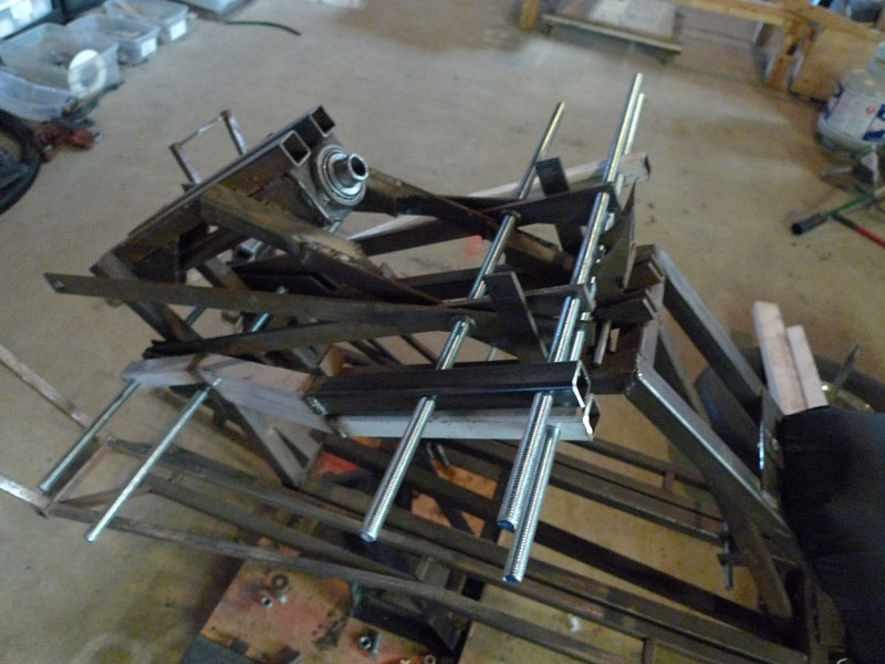
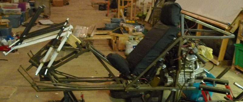
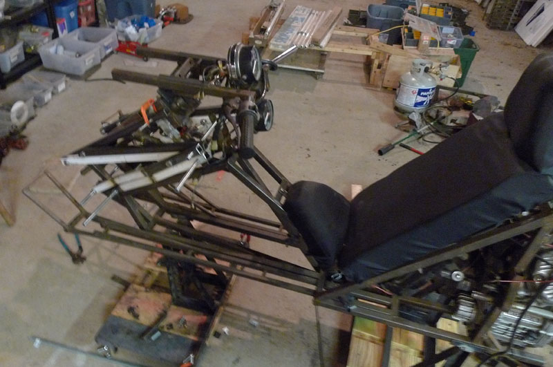
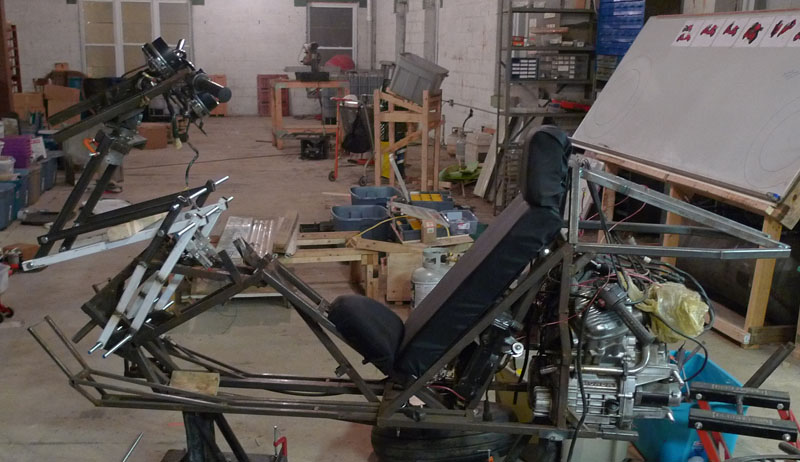
I put the front back together, and am working on the rear
Another view, the cage around the engine clamped on.
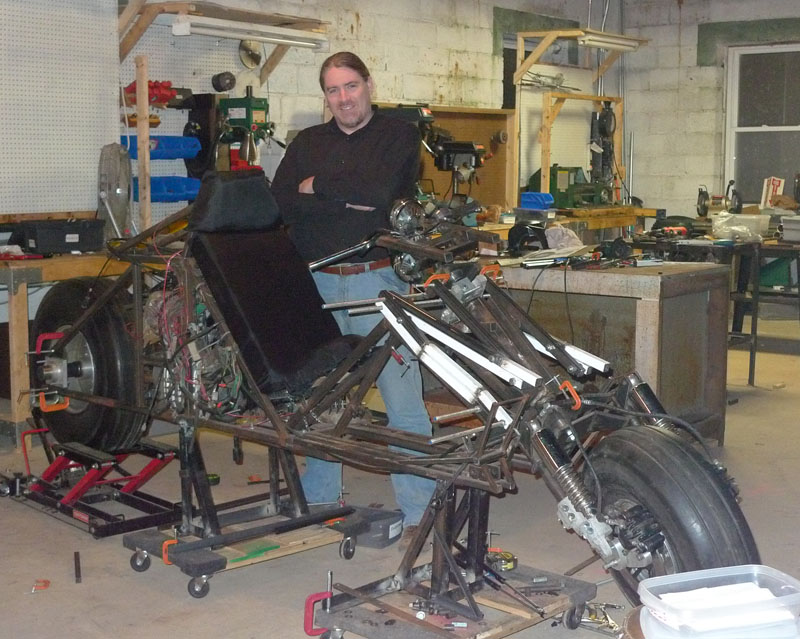
All together! Almost a rolling chassis
A sped up video assemlbing the bike
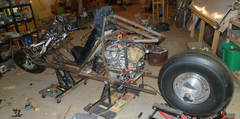
Some more views...
This prototype is a hardtail build, as I iron out front end issues I will probably triangulate the rear and add a simple shock.
The rear end has a lot of extra room to facilitate a gear reduction assembly (to compensate for the larger tire and greater weight)
A cool view...
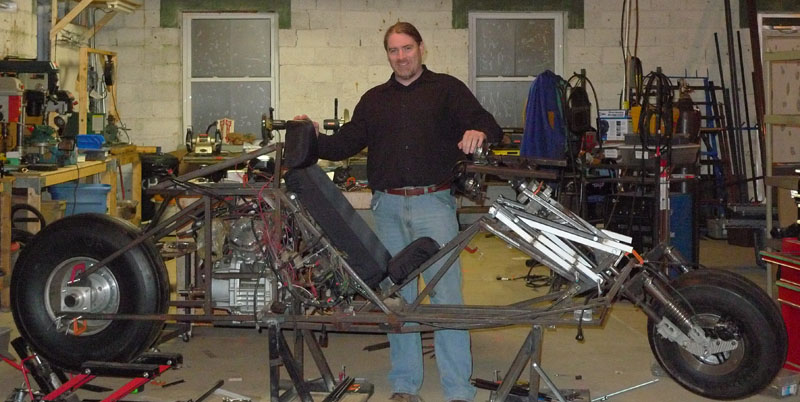
Me with the prototype
Me again...
Please LIKE the Matus1976's Akira Bike Project in Facebook to help the project out.
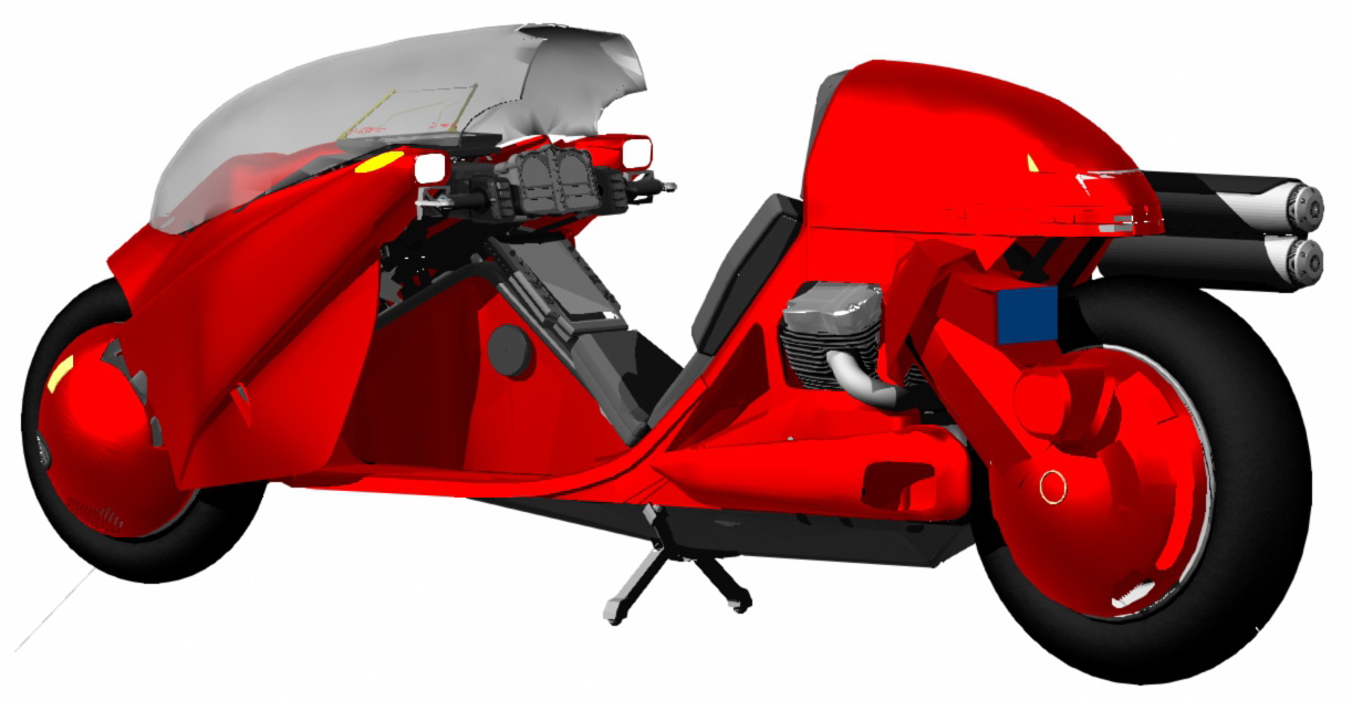
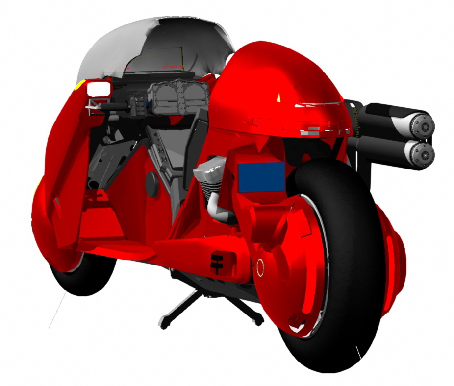
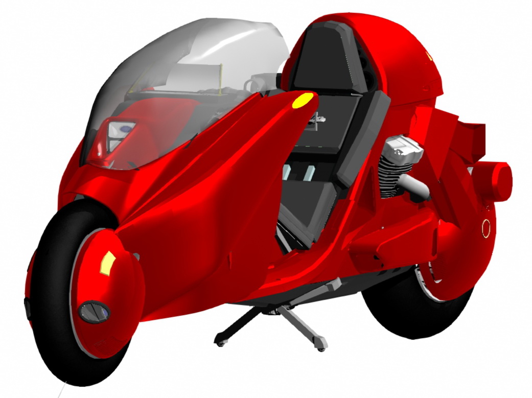
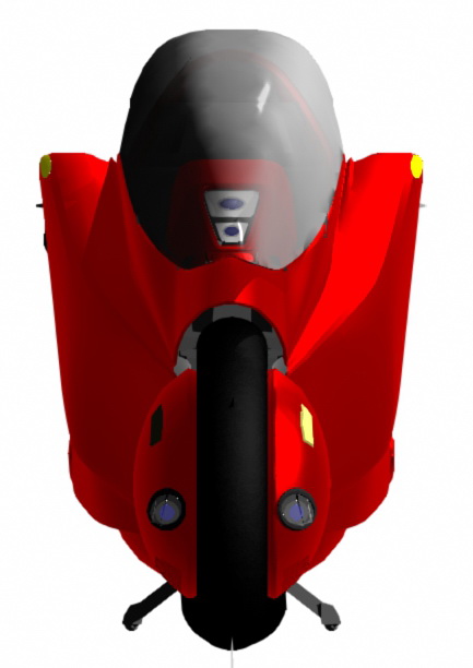
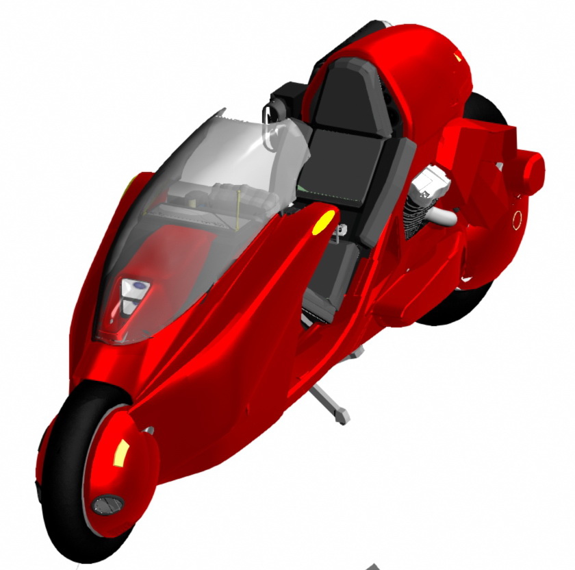
Production Prototype (in case you missed it in the last 2 updates)
This is a highly detailed and accurate 3D model of the current production design, some changes will come about as a result of further testing of the prototypes but this represents very closely what the finished product will look like.


 First I had to get my small bandsaw to cut a good square edge, above is the result after an hour of alingment and a dozen test cuts...pretty decent.
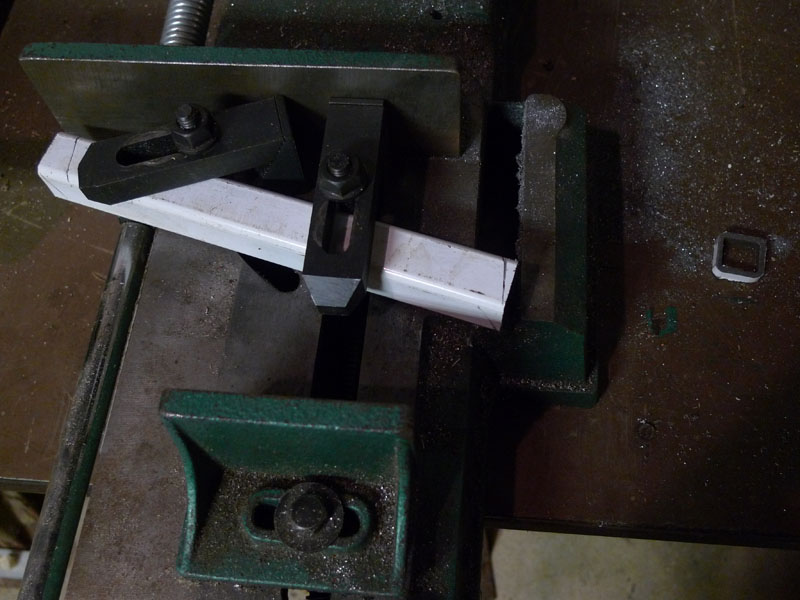 The bottom pairs of bars have an angled section to increase the width, here are the ready cuts. I found the clamps from my milling machine much easier to work with here than the built in clamp
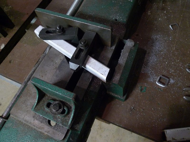
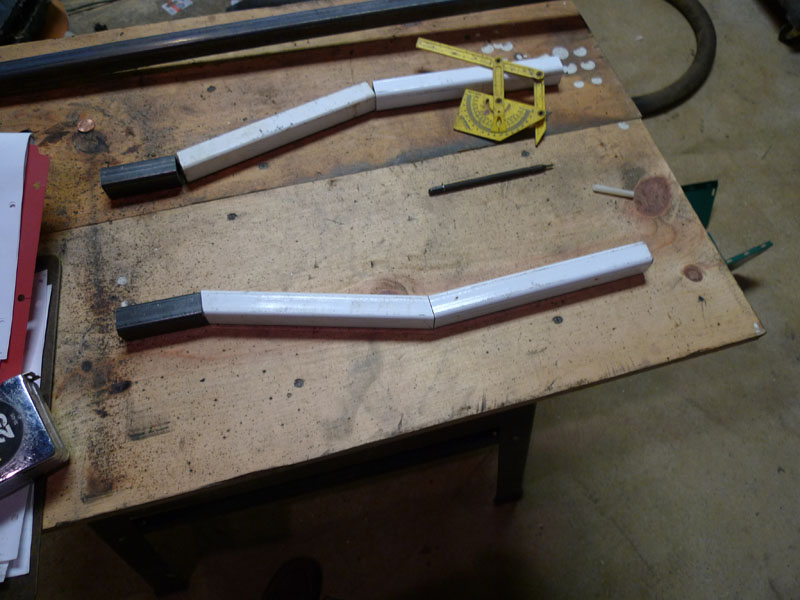 Here is one of them cut and both pairs of bars lined up
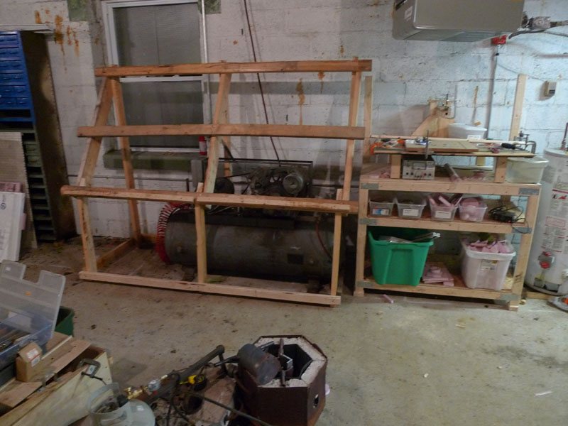
 Both pieces now complete
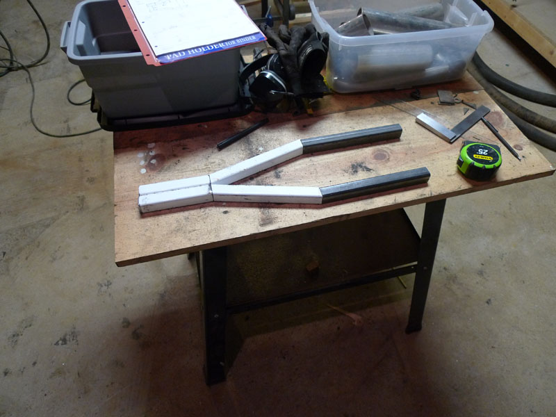 The next pair is almost the same
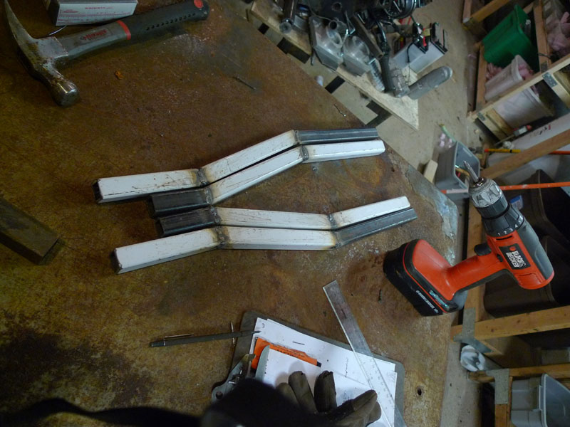
 The next six bars are straight shots, but everything has to be cut and measured and especially drilled with a high degree of accuracy for all the rotational points to work out well.
 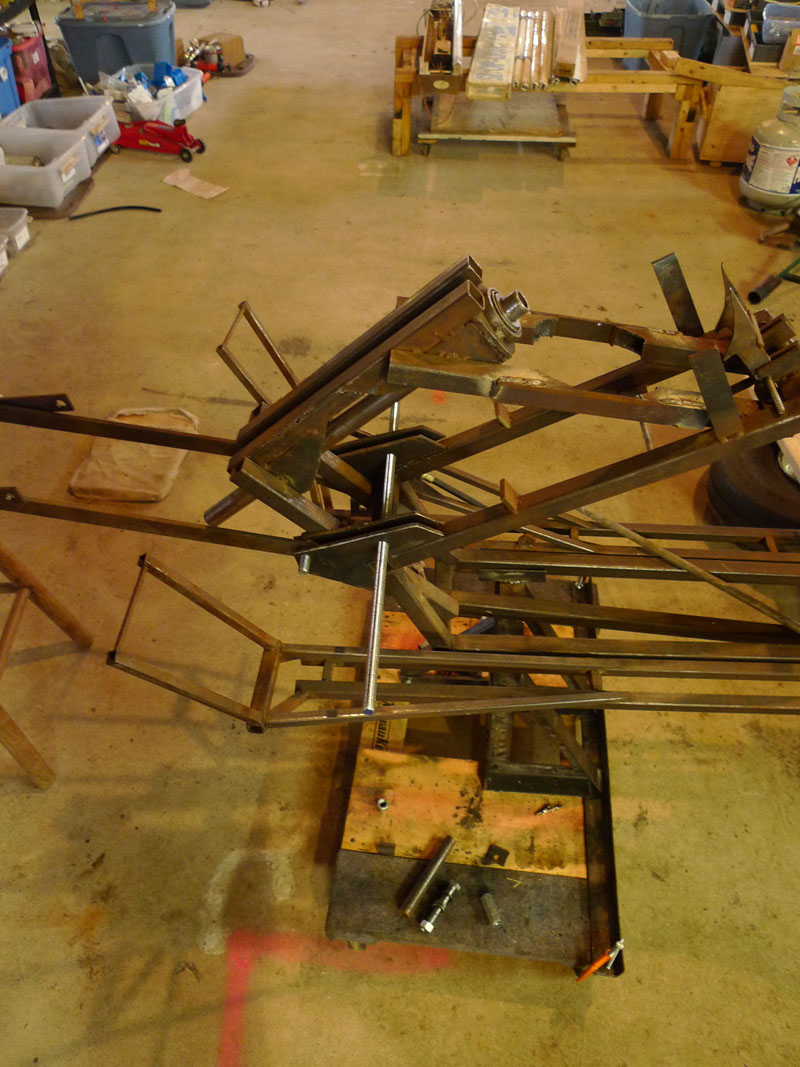 The old bars have all been stripped off and I've inserted two threaded rods to ensure alingment with the mounting bracket.
 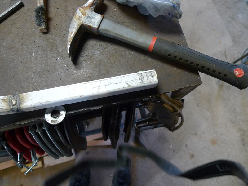 Now the hard parts, centering and lining up the holes. The first once just needs to be centered along the length of the tube.
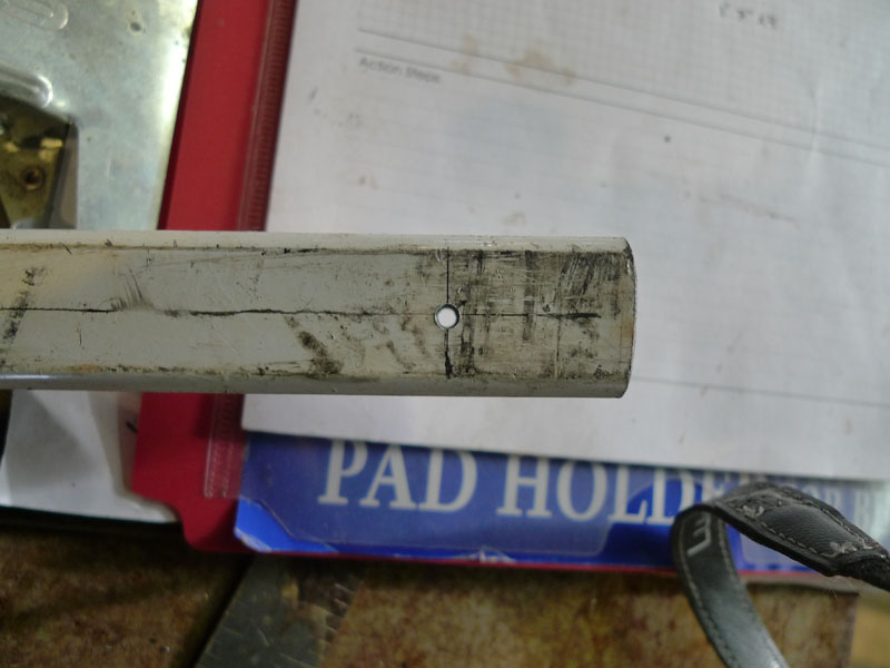
 Now it's mounted onto the bike. I replaced some of the other bars for reference to make sure everything continues to line up.
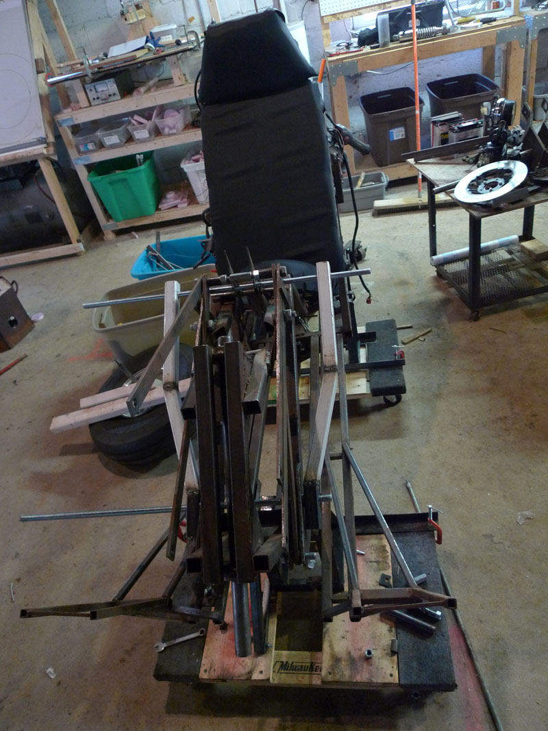 The other side is done and drilled now as well. Everything still works well.
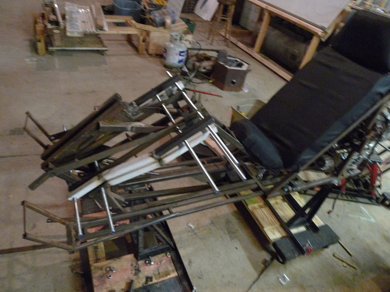
 The other side is done, here the assembly is slightly raised up. Note the narrow bars are still present. They will be removed.
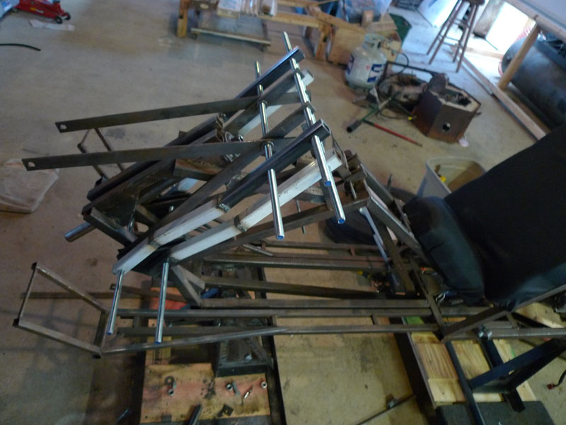
 Now the actual handlebars are added
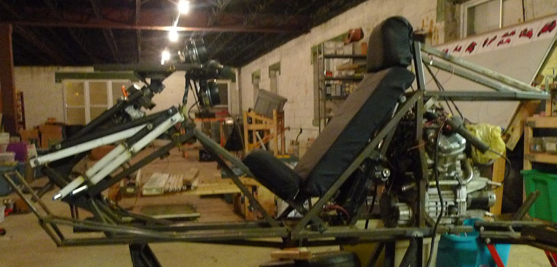 Side view with handlebars
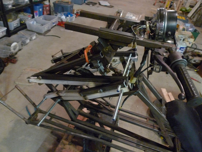 Close up.
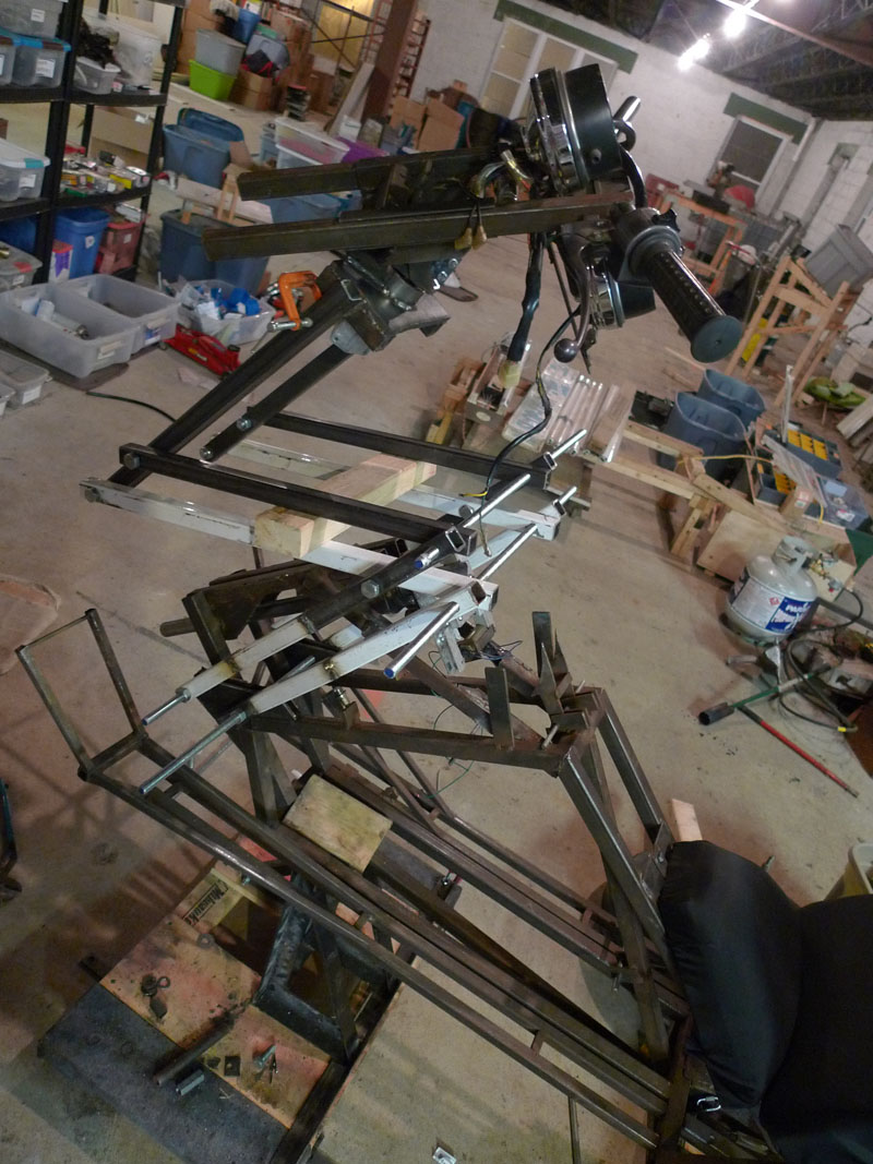
 Looks good though. The problem was the stiffness in the upper most pair of bars that attatch to the handlebars. When you pull down, the play in the bars and holes and threaded rods conspire to not close the assembly as a set of parrallel bars, instead they bump into each other and stop closing. After I weld the center tubes I expect this issue to go away.
 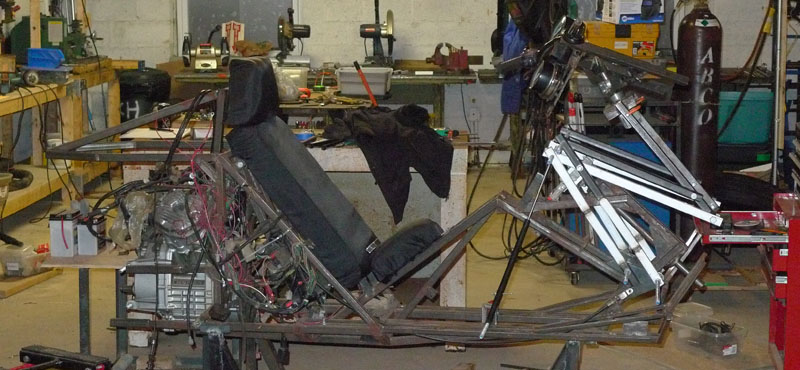 Other side, VPP raised with Gas Shocks holding it up.
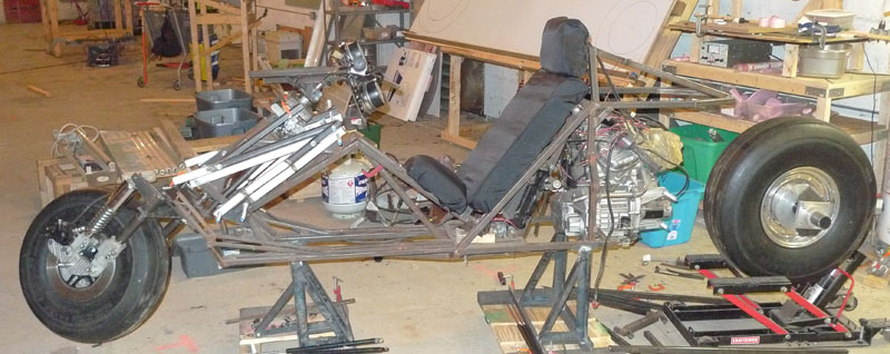
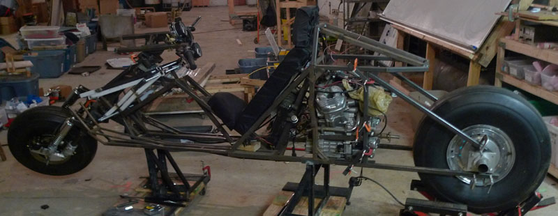 All together! Almost a rolling chassis